NeoPixels Revealed: How to (not need to) generate precisely timed signals
There is an easier way to drive NeoPixels using code that…
- is simple to understand
- easy to change without breaking
- allows indefinitely long pixel strings
- addresses the root cause of signal reshaping glitches
- needs only a trivial amount of memory regardless of string length
Here is a demo of a 1,000+ pixel string being driven by a vintage Arduino DueMillinove at about 30 frames per second…
The program only uses about 5% of this Arduino’s 1K RAM. Since the amount of RAM used does not grow with the number of pixels driven, the limiting factor for this string length was the length of my apartment.
NeoPixels are not that hard
Much has been written about how picky NeoPixels are about timing. According to the excellent AdaFruit Uberguide, “the control signal has very strict timing requirements” and people have used many exotic and complex methods to meet these strict requirements- including cycle counting, PWM, SPI, and even UARTs with extra inverter hardware.
The standard way to drive NeoPixels with an Arduino is using the AdaFruit library which has some very fancy assembly code that was meticulously hand crafted to get every tick to land in precisely the right place. This time-tested library works great and if it suits your needs then you should by all means use it- but woe to he who would attempt to try to change even one line of it.
Unfortunately I could not use this library for my project anyway because it needs 3 bytes of RAM for each pixel (one byte for each R, G, and B value) in the string. It needs all that memory to get everything ready so that it can dump all the pixels as one giant, perfectly timed bit squirt. My display had 1,440 pixels, so no way this was going to work with on my humble Arduino with 1K of RAM.
Luckily, it turns out that NeoPixels are not really that picky about timing once you get to know them.
Here is the canonical WS2812 timing diagram from the datasheet… 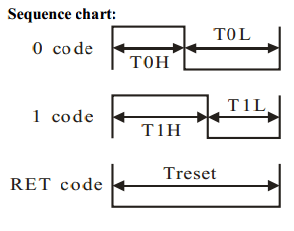
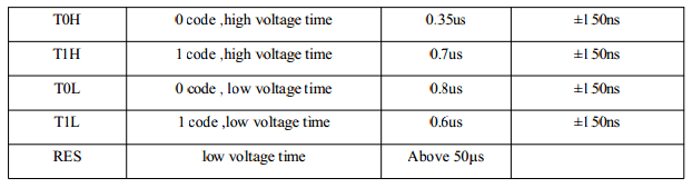
Official WS2812 Timing specs
Let’s restate these as normalized values…
| Symbol | Parameter | Min | Typical | Max | Units |
| T0H | 0 code ,high voltage time | 200 | 350 | 500 | ns |
| T1H | 1 code ,high voltage time | 550 | 700 | 850 | ns |
| T0L | 0 code , low voltage time | 650 | 800 | 950 | ns |
| T1L | 1 code ,low voltage time | 450 | 600 | 750 | ns |
| RES | low voltage time | 50,000 | ns |
This looks pretty constraining, but if we look closely we can see that things are not as bad as they seem. In fact, we’ll see that most of these apparent constraints are irrelevant.
If we instead think about how the different parts of the signal relate to each other, we can deduce that the important timing constraints for driving a single NeoPixel are…
- There is a minimum width of a 0-bit pulse (T0H) to ensure it is detected
- There is a maximum width of a 0-bit pulse (T0H) to ensure that it does not become a 1-bit
- There is a minimum width of a 1-bit pulse (T1H) since it must be long enough to not be a 0-bit pulse.
- There is a minimum time the level must stay low between consecutive bits (TxL), which ensures that the chip sees separate bits rather than one long bit.
- There is a maximum time the level can stay low (TxL) before a reset is triggered and any loaded data is latched and displayed on the LED.
That’s it! Let’s update our timing diagrams based on this new perspective…
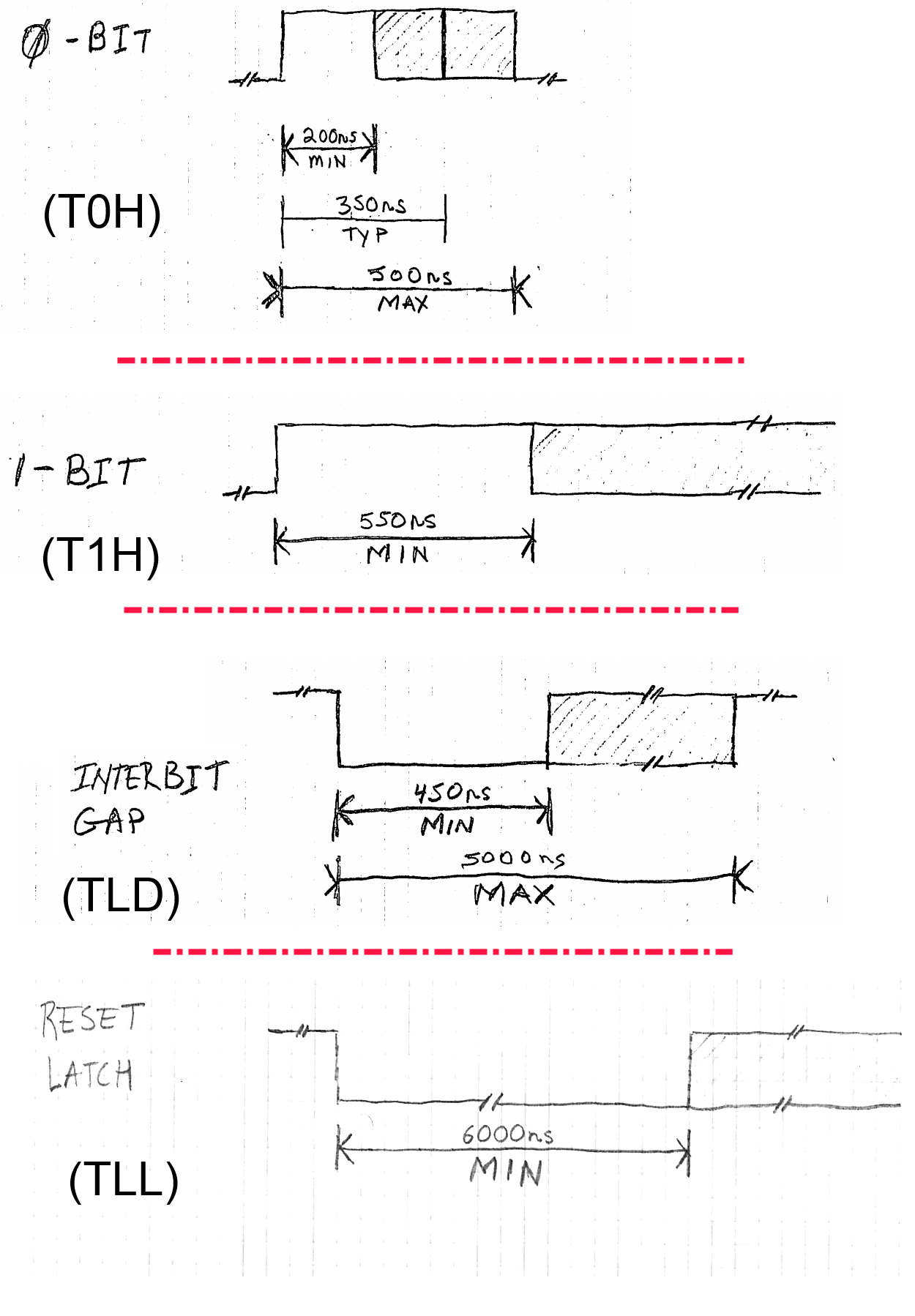
Simplified timing constraints for a NeoPixel
| Symbol | Parameter | Min | Typical | Max | Units |
| T0H | 0 code ,high voltage time | 200 | 350 | 500 | ns |
| T1H | 1 code ,high voltage time | 550 | 700 | ns | |
| TLD | data, low voltage time | 450 | 600 | 5,000 | ns |
| TLL | latch, low voltage time | 6,000 | ns |
It is easy to comply with minimums because all we have to do is not be too fast. We can waste time in delays loops, or just do other things that take a while to make sure that we don’t arrive to the party too early.
Of the two maximums, the data low time (TLD) is very easy to comply with since 5,000ns is an eternity for a program.
So, we are left with just the single tight maximum of 500ns for a 0-bit pulse (T0H). This is 8 cycles on an 16MHz CPU. That is a pretty tight constraint, but we can do it especially since it is completely deterministic and we do not need to do any computation between the start and the end of the pulse. Heck, the AVR in an Arduino can toggle a bit from low to high and back again in 4 cycles if you are careful, so we have time.
The only tight timing parameter for NeoPixel signaling is the maximum width of a 0-bit pulse
Seriously – that is all you need to do to drive a NeoPixel!
UPDATE 11/2/2020: There are some new WS2812B and WS2813 chips that require a minimum 250,000ns latch time. If you are seeing lots of flashing, you might have some of these new chips so try increasing the latch low time. More info here.
You expect me to believe there is NO maximum width for a 1-bit (T1H)?
There is no bound for the maximum width of a 1-bit that a Neopixel will accept. I’ve tested 5-second long bits, but I am confident that you can send a full pixel with 2-week long 1-bits into a Neopixel and it will (eventually) display it just fine. Test it yourself.
However, if you try to drive a string of Neopixels, group dynamics come into play and these jumbo sized 1-bits it will not work. To see why, check out…
NeoPixels Revealed: Going NSA on pixel-to-pixel conversations
The short answer is that the first NeoPixel will “reshape” the oversized 1-bit by shrinking it down to a normal-sized 1-bit. This leaves a low gap after the bit. If this gap is longer than ~6,000ns, it will become a reset pulse (TLL) to the next pixel in the string. So, while there is no maximum width for T1H for a single NeoPixel, if we want to have a string of NeoPixels then we need to make sure that no chip in the chain sees an inadvertent reset pulse. This creates a dynamic maximum for T1H in a string of pixels of 5,000ns (maximum low time before causing a reset TLD)+550ns (the minimum width of the reshaped 1-bit T1H) = 5,550ns. Luckily, 5,500ns is still a very long time and so very easy to comply with.
| Symbol | Parameter | Min | Typical | Max | Units |
| T0H | 0 code ,high voltage time | 200 | 350 | 500 | ns |
| T1H | 1 code ,high voltage time | 550 | 700 | 5,500 | ns |
| TLD | data, low voltage time | 450 | 600 | 5,000 | ns |
| TLL | latch, low voltage time | 6,000 | ns |
But wait – what is this 6us minimum for a reset latch about? The datasheet says a reset takes 50us!
I know… and 44,000ns is a pretty big signal to loose!!
If you look at the timing diagram, you should see that the maximum width for TLD is really the same thing as the minimum for the TLL latching reset code. If the signal stays low for too long after one bit is finished and before the next bit starts, then the chip resets and latches. It turns out empirically that the maximum TLD width is about 5-6us despite what the datasheet says. Really. Leave the signal low for just 6us and the LED will latch.
Just to be sure I wasn’t missing something, I put a photo-detector in front of a NeoPixel to see exactly when and how it was really turning on.
Here is a typical shot of a pixel getting latched…

TxL time needed to latch new color
| Channel | Color | Connection |
| 1 | Yellow | TRESET trigger (~6us wide) |
| 2 | Blue | DIN Pixel Data |
| 3 | Purple | Actual LED output |
The yellow trace is a trigger I put in so I could catch just the right moment. It signals the end of a full frame of pixel data. The actual data bits are in the middle trace. In this case, you are seeing the trailing end of a frame that turns the pixel from off to on. The top trace is the measured light output from the LED. You’ll see there is a pause in the data of about 6us, followed about 30us later by the LED actually displaying that new data and turning on. No 50us reset anywhere. All it takes is at least 5-6us (I use 6us to be safe) of low time to latch a new color.
But what is that 30us delay between the latch and the actual display of the new color? Maybe that is where the 50us in the datasheet comes from? Maybe, but it turns out that 30us has nothing to do with the reset timeout – instead it actually comes from the chip’s PWM circuit. If you want to learn more about that, you’ll have to read…
NeoPixels Revealed: Getting physical to uncover PWM Secrets
And now for the code…
With all this in mind, we can write some very simple Arduino code to drive NeoPixels…
https://github.com/bigjosh/SimpleNeoPixelDemo/blob/master/SimpleNeopixelDemo/SimpleNeopixelDemo.ino
Download this program and open it up in your Arduino IDE and change the #define PIXEL to match your string length and update the PORT, DDR, and BIT defines to match your board and pin.
I’m sorry that you have to look up the PORT values for your Arduino (which turns out to be non-trivial!), but there does not appear to be a clean way for the code to to do this without bringing in something like the DigitalFastWrite library, which would overly complicate things.
The top part of the demo program is the same code shown above and the bottom part is a rework of the AdaFruit strandtest program just to give you something familiar to start with. Keep in mind that I picked values that would look good on a huge string, so if you connect it to a 60 pixel strip that you might not be visually impressed.
This code should work unchanged on any AVR CPU that can toggle the 0-bit fast enough to meet the T0H maximum (that includes all Arduinos). This code is optimized for readability, simplicity, and changeability rather than speed. That said, it is still plenty fast and probably within 25% of being as fast as possible. I’ve also found that this technique of generating pixels on the fly encourages a more functional-ish programming style than working with buffers. This style often leads to code that ends up having faster refresh rates overall even though the per-bit times might not be as fast as the hand optimized bit-banging out of a buffer. It also turns out that having some slop time after each bit is actually helpful for making very long strings stable…
NeoPixels Revealed: Why you should give your bits room to breathe
FAQ
Q: In the video, when the entire strip is lit full white, it looks like the far end has a orange tint to it. Is this an artifact of the camera or something?
A: Wow, you are very perceptive! Yes, the string did start to get orange at the end at full power. I actually didn’t just run out of apartment when making this long string – I also ran out of power supplies. I had 3 supplies, each 10amps. This is almost enough, but not when every single LED is full brightness white. When that happens, the voltage at the very end of the strip starts to get too low and the LEDs start looking pallid. Why orange? Because blue LEDs need the highest voltage drop to light so when the voltage sags they are the first to go followed by the greens – leaving yellows to oranges and ultimately red.
Q: Are you really, really sure that the reset pulse doesn’t have to be 50us long? ‘Cause that could make my display silky smooth!
A: I’ve tried lots and lots of NeoPixels and WS2812’s and I can not find one that needs more than 6us of low signal to latch. If you find one that needs longer, please let me know!
Q: I have some interrupt timing sensitive code that I have always wanted to run while also driving NeoPixels. Are you saying this might be possible?
A: No problem! As long as your interrupt service time is shorter than ~5us, you can leave interrupts on while driving your NeoPixels with the above code! The only place where we turn them off is during the 350ns + 4 cycles when we are actually generating a 0-bit pulse to make sure that it stays below the maximum T0H length.
Q: Can I call SendPixel() from inside a blocking interrupt routine?
A: Since sendBit() blindly disables and re-enables interrupts, it will blindly turn interrupts back on every time it sends a 0-bit. This is easy to fix. If you are going to always be sending bits from inside a blocking interrupt routine, you can just totally delete the cli() and sei() since interrupts will already be off. If you want to send both normally and from a blocking interrupt, you could store the interrupt state and then restore it rather than blindly sei()’ing.
Q: What NeoPixels are you testing with?
A: I’ve tried every WS2812 I could get my hands on, including lots of NeoPixels from AdaFruit, eBay, and Alibaba. If you find some picky NeoPixels that I missed, please let me know!
Q: Where are your favorite places to get your NeoPixels?
A: Of course I love AdaFruit because they are awesome, have great prices, and ship from NYC in 1-2 days. For huge bulk orders or when I need something special that AdaFruit doesn’t sell, I also have been super-happy with Mr-Right-LED because Mr. Zhang can make me 96 LED-per-meter strings just the way I like them with no silicone, heat shrink, or adhesive – and they also have great prices and ship from Hong Kong in 2-3 days.
Q: Could I save time by using the gaps in between individual bits for image computation rather than waiting until the end of a pixel?
A: If your algorithm is fine grained enough to be efficiently broken into 24 very short work units per pixel, then this could be tremendously efficient -and impressive! Please send what you come up with!
Q: Silly question, but what if I want to show video!?!
A: No problem, just use Flash! Arduinos have way, way more Flash than they do RAM so there is plenty of room for video data especially if compressed. Read the video data out of flash, decompress it, and send it to the NeoPixels on the fly. No frame buffer needed as long as you can beat the generous 5us timeout. You will probably want to write a program in Java or Python to generate the PROGMEM C code with your compressed video data in it. Ognite uses this read-video-data-on-the-fly-from-flash technique, so is a good place to look for example code. If someone comes up with some super awesome video source material maybe I’ll build an example project to show exactly how it is done.
Q: So it seems like serial communications is not possible while updating the LEDs since interrupts must be off?
A: Is is hard, but not impossible! You can not do normal interrupt-based serial, but you can do polled serial if you take advantage of the fact that the serial ports on the AVR’s have a hardware buffer that can Read and decode serial data in the background automatically. As long as you read the data from that buffer before it gets covered by new data, then you have serial.
If we assume only a 1 byte buffer (the ATMEGA328 in the Arduino Uno has 2 bytes), then probably the easiest way to get interrupt-free serial communication working is to make a very simple protocol where every byte sent to the Arduino is acknowledged by a byte send by the Arduino. So let’s say you wanted to send the string “HELLO” to the Arduino from your laptop, the serial data going back and forth would look like this…
L: 'H'
A: '+'
L: 'E'
A:'+'
L: 'L'
A:'+'
L: 'L'
A:'+'
L: 'O'
A:'+'
See how that works? As long the laptop waits for the + to come in before sending the next byte out, then it knows that the receiving buffer on the Arduino is empty and ready to receive the next byte.
You can implement more complicated protocols by having the Arduino send other stuff back besides just + just as long as there is a ping-pong effect that prevents the laptop from sending a byte before it knows that the byte before it was read out of the buffer by the Arduino.
Alternately, you can just pick a serial baud rate that is slow enough that you know that the laptop can not push bytes down the serial link faster than the Arduino can read them out of the buffer. This baud rate would be limited by how long interrupts are off while updating an LED string.
In either case, you likely want to ditch the Arduino Serial stuff and go straight to the hardware since it is much simpler. LMK if you want to see come example code.
Q: This code does not compile for my [you not-Arduino-Uno board here]!
A: This code is hand crafted specifically for the chip on the Arduino Uno. It is very unlikely to work with any other chip, and therefore boards that uses a different chip. It is probably possible to get it working with other chips in the AVR8 family, but would take work. For other kinds of chips, you would need a completely different strategy.
UPDATES:
11/2/2020- Added info on the new chips that require a longer reset pulse.
2/16/19 – Added FAQ on other non-Uno boards.
11/11/2018 – Added FAQ on serial communications.
3/13/2015 – I’ve updated the code on GitHub so that it now compiles correctly on all version of the Arduino compiler. I had to get rid of the calls to _deley_cycles() because this function seems to be missing on some version of the OSX compiler. It is instead replaced with some (very simple) inline assembly. You can see the code changes here.
7/8/2014- Thanks to Hack-a-day, I found Tim’s similar work on WS2812Bs. He was motivated to optimize for speed and efficiency, but ends up with code that is also simple and elegant. If you are looking for code that is all C and easy to play with and understand, then my code is good – but if you want a fast library to use in production then you should check out his excellent library.
6/12/2014- Updated the code snipit on this page to match the code in the demo project on GitHub. The timing constants have been relaxed even further (things that have minimums are longer and things that have maximums are shorter) based on feedback I’ve gotten from people running the code on lots of different WS2812’s from lots of places. The code overall now takes slightly longer, but should work with any chip no matter how how sloppy they are.
Thanks for all the great info! I am looking into using a lot of neopixels to indirect light a cofferred ceiling in a room addition we are planning. I do software and know too little about the hardware side, so I am a little concerned about doing the right thing for powering this project… that’s a lot of current! I may do 5V power supplies around the loop or was thinking about running 12 or 24VDC and using buck converters for the 5V. so I am thinking I want a continuous run for the ground and data line, but break the 5V line where each powersupply is inserted.. is this the right way to power a 30+ foot string? Can you point me somewhere to understand how this is done?
Thanks for the help and all the great content!
I prefer to keep the distribution voltage as high as possible and then drop it down when it gets to where I need it, so I’d use 5 volt power supplies near the pixels they are powering. This lets you use much smaller distribution wires (12 volts needs 10x more current than 120 volts to transfer the same power), and also skips the extra equipment and losses of the buck converters.
You do want to connect ground and data lines between adjacent strips (data line is not really “continuous” because it is generated at the output each pixel). You could split the power segments, but this could lead to a problem if two adjacent strips end up at significantly different voltage levels because, say, one happens to have all LEDs on bright while the other happens to have all LEDs off.
Long story short, you can end up with a case where the voltage of a data in pin on the pixel next to the break is much higher than the power supply voltage that pixel is getting. This is not good.
If you always connect the power supply pins together, then adjacent pixels will always have power voltages (and thus data voltage levels) that are very close to each other.
Luckily, NeoPixel strips have pretty high resistance so as long as there are a couple of strips between power supplies, then the resistance of the strips will prevent the supplies from fighting each other too much even if they have slightly different voltages.
Let me know if this doesn’t make sense and I’ll do a diagram that will hopefully explain better.
Thanks again for this information. Exactly what I wanted to know. Now I can run NeoPixels on a JeeNode, too, with interrupts enabled for RFM12b reception. Sweet.
Chris,
I’m working on a similar problem: WS2812 and RFM12B on a JeeNode. Would it be possible to send me a link to your solution–that’s surely close to what I’m after.
Warm Regards,
Mike
Hi Mike. I’m now using FastLED ( http://fastled.io/ ). The core update loop does turn off the interrupts for a while, but I didn’t have problems with that so far. You could modify the code though that it enables the interrupts after each LED for a short time (in pin low state though), so that the RF12 interrupt has time to read out a byte during reception.
Cheers, Chris
Chris,
Thanks. My concern would be that if a packet comes into the RF board during the cli()/sei()-protected WS2812 updates in FastLED, the RF board will throw an interrupt… which is ignored/dropped. While we can work to minimize the interval of time, I think we’re always left with some interval where a radio interrupt is dropped?
The only path forward I can see is to recode the RF library to move away from interrupts and use polling approaches instead.
That said, if you’ve got a working amalgam of RFM+WS2812 library code that “plays well together”, I’d love (love love) to see how you fit those pieces together. Do you have a github repository that I could reference, please?
Regards,
Mike
Ok, so it is actually possible to drive NeoPixels without turning off interrupts at all by using the Timers to drive the data bits. Since this seems to be coming up a lot (especially people wanting to receive RF and serial while fiddling NeoPixels), I’ll go ahead and do a quick article showing how it is done!
bigjosh2,
That’d be huge, thank you. ISR’s are more straight-forward than internal peripherals (and possibly easier to port around hardware), but running multiple devices requiring ISRs is quite difficult.
Another option using internal peripherals would be most welcome. Please let us know where that post goes up!
Regards,
Mike
So, I’ve written some code that effectively eliminates any interrupt latency due to the neopixels, but there are two problems remaining. (1) The Arduino’s normal timer that keeps track of ticks for the millis() function and other things makes more than 5us of latency on its own, (2) the RTM library also causes more than 5us of latency. So, you could comeplete disable (or rewrite) the Arduino clock, but you’d still have to live with corrupted pixels anytime the RF code was receiving. i did look at the RF code and I think it might be possible to rewrite it for acceptable interrupt latency, but it would be a lot of work.
After some research, I now think it is impossible to write any practical code that is dependent on exact timing and sequence in AVR-GCC (the compiler used in the Arduino IDE) because there is no way to prevent the compiler from rearranging the order of operations when it optimizes. You might be able to craft a piece of code that happens to result in the correct order of operations for a specific compiler version with specific settings, but it is just luck and there is no guarantee that the same code will continue to work correctly with other versions/settings.
My new strategy is to generate the critical timing sequences using the chip’s Timer2 hardware. The output of this unit is precise to a single clock cycle (62.5ns with a 16Mhz clock) and completely deterministic. Also, once started it will run completely independently of any code that is executing so you can even do simultaneous foreground processing and completely turn off interrupts. As long as the system clock is running, the correct pulse length will go out.
BTW, I know that many people use this code so they can respond to latency sensitive interrupts (i.e. RF reception) while also driving NeoPixels. While the current code is succeeds in keeping interrupts enabled while driving the NeopIxels, it is still possible that the NeoPixels output can be corrupted because the RF receive routine turns of interrupts long enough to cause the NeoPixels to reset. There is not much you can do about this without re-writing the receive code, but at least with the new Timer2-based approach you can detect when this happens and limit the damage to a single pixel, and then immediately try to refresh the NeoPixel string again with the correct data.
I hope to have an article with code up by next week!
Thank you for the amazing in-depth tutorial, I stumbled across it as I am starting to have trouble with quick animations on my 900 neopixel christmas light strip. I downloaded your code off GitHub, however when I compile it I get an error in DelayCycles that __builtin_avr_delay_cycles is not defined in this scope. Any help would be appreciated.
Looks like I had an outdated version of the compiler. 1.5.8 compiles no problem.
Ok, after beating my head against a wall I still can’t get this to work :( I have tried it on a Yun, Mega, and Uno, and I can’t get much of anything to happen. At best a few pixels will light up pure white and that is it. I have tried multiple strings as well (https://www.sparkfun.com/products/12028).
Any help would be appreciated. I have no issues with the Adafruit library, and light_ws2812 works, but only for strings < 256 pixels.
It looks like you are using a mac? The mac version of the Arduino IDE has a broken compiler (see FAQ above). Either you can email me the code and I’ll try it on my PC- or I can convert the timing critical part of the code to ASM- which will work but loose some of the aesthetics.
Yes, I am using a Mac, 10.10.1. I’ll fire up a PC and give it a try and report back.
The code here is good to start fiddling with NeoPixels. But I then found a library called FastLED, which also supports the NeoPixel protocol but additionally has all sorts of support routines, such as fast 8 bit maths and HSV colour space. Works like a charm both on my NeoRings and NeoMatrix…
You could give it a try — fixing the mac compiler is recommended nevertheless…
I’ve just updated the code on GitHub and it now compiles on OSX fine.
What is the SimpleNeoPixelDemo code licensed under? Would you mind licensing it under an open source license that is compatible with GPLv3 to me? Thanks.
It is licensed under “Use it however you want, just don’t copy it exactly somewhere else and claim it is yours”!
Hi I’m trying to get this to work with the Trinket ATtiny85 and I can’t identify the correct port mapping. I have the data output connected to pin0 on the Trinket but I’m lost as to what entry I would need to make under the port settings in the code. Any help greatly appreciated.
Looking at the Trinket pinout here…
https://learn.adafruit.com/assets/13866
It looks like the Trinket Pin #1 is on PB1. This means “Port B, bit 1” on the chip. So, the corresponding NoePixel code would look like this…
// These values depend on which pin your string is connected to and what board you are using

// More info on how to find these at http://www.arduino.cc/en/Reference/PortManipulation
// These values are for digital pin 1 on an AdaFruit Trinket
// Note that you could also include the DigitalWriteFast header file to not need to to this lookup.
#define PIXEL_PORT PORTB // Port of the pin the pixels are connected to
#define PIXEL_DDR DDRB // Port of the pin the pixels are connected to
#define PIXEL_BIT 1 // Bit of the pin the pixels are connected to
Note that the Trinket only runs at 8Mhz, which is just barely fast enough to make the required signals. It is possible to speed the Trinket up to 16Mhz with some code if there are any problems.
Let me know if it works!
bummer about the interrupt issue, i can’t imagine writing real programs leaving interrupts off. i’m a very big proponent of “cooperative multitasking”, “tasks” coded as state machines that never (never) block — but as you say, radio and inter-processor serial needs interrupts for character reception and transmission and cli() kills the deal.
nice work though!
It is possible to only turn of interrupts long enough to send a full pixel. This way, if you do get interrupted then the worst that can happen is an inadvertent RESET, which at worst will not update the full string but each pixel will still be showing a valid (albeit possibly stale) color. You can then attempt to refresh the string again and visually everything will likely look fine as long as you don’t keep getting interrupted again and again.
I’ve never tried this but you should be able to “freeze” transmission while the data line is high and enable interrupts. You could then do one or two nops to allow the interrupt to be detected if one is pending. then re-enable interrupts and continue with your transmit. While the WS2812 data line in high, no data is lost, and you can pick up where you left off. I will not effect any timing on the WS2812. All you have to do is figure how often this procedure is required to not miss any interrupts and how to stick it in the library.
Unfortunately this does not work. If you hold the line high for any significant amount of time, you will end up with a reset on any pixels after the most recently addressed one. This happens because the stretched out high is converted to a low by signal reshaping in the most recently addressed pixel. See Going NSA on NeoPixels here…
On strategy that does work is to check for a pending interrupt after each pixel. If there is one, then stop sending, go into reset, enable interrupts. When the pending interrupt is complete, you restart sending again from scratch. This works fine as long as the interrupts don’t happen so often that it visually messes up the string because, say, you almost never get to send a full set of pixels. This obviously becomes more of a problem with longer strings since it takes long to send all the data.
I’m using some of your demo code in a project of my own! I ported the base code to ATtiny and removed the Arduino dependencies, and its running inside of a Gamecube controller.
http://electricexploits.net/shinewave/
https://github.com/GGreenwood/Shinewave/blob/master/libs/Neopixel.cpp
https://github.com/GGreenwood/Shinewave/blob/master/libs/Neopixel.h
Hi Josh,
Thanks for the great NeoPixels posts. They really helped me out with my PIC Microcontroller WS2812 driver. I did run into some real-world limitations that made me tighten up my timing (500ns T0H didn’t work on all my strips).
I wrote this up and linked to a couple of your posts. I hope I gave sufficient credit. Have a look if you get a chance. I would love your feedback and will update my post accordingly.
Here it is: https://www.linkedin.com/pulse/ws2812-dummies-tom-roden
I’m not an engineer, nor understand coding….I’m looking for noepixel strip weatherproof lights to go on my houseboat at lake mead. I am in need of 150′ roll or can split that in half and do 2. I have tried rope light, the sun beat them up and only lasted a year. I tried purple led rope in tracks, and only lasted a year. I’m now on heavy duty RGB with controller and I have about 4 sections that are burnt out.
So I’m in need of really awesome lights that will last.
Sounds like a very rough environment. You can try the pixel strips that are encapsulated in epoxy (example here). You could also try the extremely robust but very expensive iColor Flex MX or LMX.
Following the impulse of your blog I finally got in the mood to finish implementing my WS2812B library: It supports color palette, and the methods can be called repeatedly to light up an infinite LED strip with a 16MHz UNO. Added bonus, bit banging is done without inline assembly, just using careful C++ coding:
https://dntruong.wordpress.com/2016/02/29/my-ws2812b-library-with-palettes
I can define 1,2 4, 8 bit, 2 bytes, 3 bytes or 4 bytes per pixel.
The demo i put on my blog uses a 12 bytes palette and 4 bytes for the 16 pixel pattern.
It’s a bit tight at 16MHz to run, so next I’d want to learn how to program PWM to shape the pulses without bit-banging. Maybe this could run on 8MHz?
Woohoo! :)
You’ve been an inspiration for me to write a new LED library that handles any number of pixels, and supports palettes. The code is on GitHUB as FAB_LED:
https://github.com/sonyhome/FAB_LED/archive/master.zip
I’d love to see you take a peek at it and get feedback on the implementation,
feature set and performance. Note I put very aggressive LED timings tested
only on strips I have on about a 160 LEDs.
I believe this library has a small edge over AdaFruit and FastLED libraries.
I’d like to learn and grok PWM programming to replace bitbanging and maybe
generate cleaner signals on even 4MHz CPUs. I’ve only tested on 16MHz
Uno and AtTiny85 so far.
The code took forever because coding after work where I code requires me to still be in the mood.
Looks cool!
I’m not sure how PWM would be better for driving NeoPixels on an AVR8. Typically you see this on ARMs that have DMA so the PWM can run autonomously. On AVR8, you’dd need to constantly keep updating the PWM manually, which would take more work than just banging the bits.
I do think you could use Blind Send SPI on AVR8 to speed things up enough to get NeoPixels working at 4MHz. But I am curious as to why you’d want to. Typically you’d want to run AVRs that slowly to either save power or to be able to run at lower voltage, but because the NeoPixels need a huge amount of power and relatively high voltage, it seems and benefits would be negligible. Is it just for the challenge?
haha yes, mostly a challenge for code optimization, but yeah you’re right I got better things to implement. I want to add pixel remapping to support 2D displays, and support other LEDs & SPI like APA102.
Josh, I would be honored if you tested out my FAB_LED library and gave me your opinion on its performance and API. I’ve only tested it at 16MHz so far without a logic analyzer on ws2812b, and today on pl9823/apa104.
Lovely code! Looks like it would be easy to add support for mixed bit-length strings to it!
Thanks. It’s a foray into C++ away from my usual C. I indeed added sk6812 support, and made a mixed bit-length example for Lukas in example A: https://github.com/sonyhome/FAB_LED/tree/sk6812
ahhh why it be gone. I’m looking for sk6812 support. I got 17 strips of 144LEDs.
I’m actually in big trouble I got a lot of time the next month. But in 1 month I need my project functioning.
Currently I could probably drive those ~2500 LEDS but only at 1FPS. how lame would that be. LMK alright
Check out…
Might be exactly what you are looking for.
My library should still be around. However 2500 LEDs from 1 16MHz AVR might be a stretch unless you want to color map or update in real time without an in-memory array.
To reduce latency FAB_LED does have a mode where it can update up to 6 ports at the same time.
I haven’t touched the library in a while and it’s still a back burner ticket item to port the bitbang loop to ARM and other chips (I just need to code a nop loop).
I’ll try it with 900 pixels this weekend
Please do keep me posted!!! (you can start a discussion on my page to not spam Josh’s).
Hello there.
Did you tested RGB-W LED named SK6812?
I’m just curious since I want to run this Red-Green-Blue-White color LEDs on single line in series with WS2812B.
Those LEDs are supported by Adafruit Neopixel library but coding is different so I have to choose whether line will be feeded by WS2812B signal OR SK6812 signal.
I think that ATtiny85 with piece of smart code can do the trick and act as converter between those two standards, so I can start with WS2812B strip, then convert its output from last pixel by ATtiny and continue the line with SK6812.
This can be done also opposite way if needed.
I know that I can simply run those strips separately using parallel wiring, but in my case it requires car interior dismantle, so that’s the reason why I’m thinking about WS2812B>>>SK6812 signal converter.
Hey, another point to think about:
If I want to leave strictly serial conducting of WS2812Bs since it is very inconvenient to direct data wire to some “leaf” and then wire it back.
Its much better to use tree topology for leafs, so there is no need for return of signal wire.
BUT: If you make leaf of 3pixels, connecting them in parallel to main LED strip, you have to sacrifice next 3pixels on the main strip and mute them by black foil to simulate illusion that leaf AND main strip are addressable individually..
This is cheap and easy while making 3pixels leafs. But become expansive and also power consuming while there is need for 30pixel leafs.
In this case it should be very handy to power tree topology by ATTiny in each node, which will “eat” the data mentioned for the leaf LEDs and forward rest of signal to next LED in the main chain.
>I think that ATtiny85 with piece of smart code can do the trick
>and act as converter between those two standards, so I can start
>with WS2812B strip, then convert its output from last pixel by
>ATtiny and continue the line with SK6812.
I do not think it is possible to convert WS2812B data stream to SK6812 format on the fly because the SK6812 need 4 bytes per pixel rather than 3. While you are sending the 4th byte for the 1st pixel, the 1st byte for the 2nd pixel will already be coming in. With each pixel you get further behind. I guess you could try to buffer the incoming data into memory, but if the WS2812B is refreshing quickly then you will eventually fall too far behind.
>In this case it should be very handy to power tree topology by ATTiny in each node,
>which will “eat” the data mentioned for the leaf LEDs and forward rest of signal to next LED in the main chain.
I do not think this is necessary – it turns out that you can directly connect the Data Out pin from NeoPixel into the Data In pins of more than one downstream pixel. It really works – I do it all the time! Of course the two stream that are in parallel will display the same patterns, but often this is a benefit.
Very odd. I have an SK6812 datasheet which describes essentially a WS2812B.
There are only 3 leds: RGB. I’m using the SK2812MINI on a project currently. It’s 3.5mm square and is in a DFN package.They are driven exactly like a WS2812. Chinese documentation, part numbering, and nomenclature is just about worthless!
Could someone point to a datasheet for this part you are discussing?
Sorry — that should be SK6812MINI
I think there are both RGB and RGBW versions. Here is the dtaa sheet for the RGBW version…
Click to access SK6812RGBW-datasheet.pdf
Hello.
Thanks for really fast reply :-)
Indeed. SK6812 could be either 24bit OR 32bit.
https://forum.arduino.cc/index.php?topic=364208.0
I’m impressed that White chip is quite powerful and its color is very natural.
But its price is doubled comparing to WS2812B at the moment.
I’m aware that its not possible to carry 4Byte information in 3Bytes.
But I was thinking that I can at least extrapolate White value from RGB.
For example (250,50,30) for 24bit strip can be considered as (250,50,30, 30) for 32bit string. Don’t you think?
Also when converting from 32bit to 24bit information, White value should be simply dropped while forwarding just RBG only.
However, my RGB-W strip is now used as addressable foot-well light in the car. More or less I use animated patterns with white light only depending on CAN-BUS information on the input.
I use also RGB LEDs for door lock handle back-light, depending on conditions. Red/Green blink while locking/unlocking car, White back-light while car is not moving, blackout while reverse-gear is shifted.
I don’t want to dismantle four doors and change RGB leds to RGB-W at the moment.
There are also WS2812 Neopixel sticks in both mirrors as animated turn signal.
Those are sealed and I use amber light only so RGB is perfect here and change to RGB-W is not desired.
I can still keep all LEDs as RGB only OR add extra wiring for 32bit RGB-W strips.
But I was just curious to discuss this option of simple 24>>32bit and 32>>24 bit convertor to run “mixed environment” in series :-)
I could extend my own library to support SK6812 including RGBW, assuming there’s interest for it and someone to test and validate it works. I do have a 32bit pixel mode already where one byte is just dropped.
Hello.
Im definitly in :-)
Please note that Adafruit Neopixel library already supports 32bit LEDs since Adafruit is selling those LEDs.
But I assume that your library should be faster and more efficient.
My primary interest is library which can read signal from last 24bit LED of my string and convert it to 32bit stream for continuing 32bit strip.
The same functionality would be benefical also opposite way. From 32bit strip output to 24bit strip input.
B.R. Lukas
I do not think it is necessary to read the signal from the end of one strip and actively convert to the next strip. You should be able to just directly connect the the two strings together and send the right data and everything will work. This is because once a pixel has read its own bits, it will blindly relay any additional bit down the line. It does not try to decode or count these bits (except for re-timing the single bits)- it just sends them on down.
I believe Lukas is talking of combining WS2812B RGB and SK6812 RGBW, in which case the signals are not compatible and the 2 LED strips need to be put on separate ports. Otherwise, if both are RGB the timings compatibility would be the only thing to consider.
With FAB_LED if you need to support RGBW, it’s easy to convert on the fly an RGB value to RGBW, assuming the W channel is just off, or requires simple math. With my library, if I add support, you would just pass the offset of the array where you’re drawing to each port.
With Adafruit if they have support, you’d have to draw 2 separate arrays.
Indeed.
In my car setup I run “main” Atmega328P which is reading signals from CAN-BUS modules and controls 4 arrays of WS2812B LED strings.
My dream is to have additional ATtiny which will be used in any point of the string as interface, when changing from WS2812B TO SK6812 signal OR opposite way :-)
I’m aware that this strange setup requires new ATtiny each time when combining 24bit LED string with 32bit one, but for me its small price comparing to add extra wiring for each place in the car where I decide to use 32bit LEDs. :-)
You would have to implement the attiny input to receive the signal from the LED strip. Doesn’t sound too difficult to do.
You would have to buffer the input and when you see a reset signal, send the bits you received.
The question is will you have time to send it as soon as you receive it.
I think it is possible.
Otherwise you would have to wait for the refresh signal which incurred a delay in the forwarding of the bits but it might not matter either for you.
Hello there :-)
As you assumed.
Time doesn’t matter, since human eye is not able to measure that differences.
I’m just dimming foot-well lights, door lock levers and animating turn signals.
Can you help me with some kick off, of ATtiny code?
For example left back seat:
I’m wiring cable under driver seat. There is node.
Two WS2812Bs for back-light of left door lock handle @left back seat.
Two hidden WS2812Bs just to eat that signal, continuing to 15x SK6812 for left back seat foot-well light.
At the moment there is 15xWS2812B, but SKxxxx is more powerful and more natural color.
Front seats works opposite way:
Foot-well light on the beginning of the strip. (SK6812)
Continue to door lock lever back-light.. (WS2812B)
Continue to turn signal in back-mirror. (WS2812)
At the moment all LEDs are WSxxxx, but it should be nice to add those with RGB-W capability :-)
Well you’ll need to do some coding for reading theLED strip output yourself, in a loop that runs about 800kHz (?) and detect zeros and ones. Zero is a short high level, and a one is a long high level.
If you have a long duration without a high level, it’s a led strip reset signal. so clear any bits you had stored.
I suggest doing this test with a arduino uno, and printing the data seen to the console with Serial, and verify it matches what you are feeding in.
Now the question is: Is adding an attiny85 in the middle of a led strip simpler than wiring the data line from the main arduino to all the led strips? Is that really a cleaner design to drop in into the car? you still need to find somewhere to hide an atiny, so why not find a way to run a hidden line?
Yes, you are right. Simplest and most reliable thing that I can do is implementing extra wiring for 32bit strips, if I need to use them. Since library is able to drive both kind of strips, this way is probably best.
However this idea has merit where the lighting patterns have to be inlined, and matched, I see some applications:
* inline Apa106 (RGB) with apa104/ws2812b (GRB) – different form factors require mix n match for some projects.
* inline SK6812 (RGB or RGBW) with apa104 – less usefull unless the RGBW is first, and W dropped, or W rebuilt from RGB value. Seems more of a special use case.
* mix Apa102 and Apa104 strips – why? maybe just because that’s what you have in stock, and willing to sacrifice a controller for that?
I think the bit timings of the SK6812RGBW and the WS2812B are compatible. The only difference in the data-stream is number number of bytes per pixel (4 four SK6812RGBW and three for WS2812B. So say you connected one long string of 8 pixels- the first 4 pixels SK6812RGBW and then last 4 pixels WS2812B. I mean literally connect them directly together, end-to-end. No extra wires.
Now you could just have the software driving the full string from the head on the ATMEGA send a total of (4*4)+(4*3)=28 data bytes and everything should work. The bytes would look like “R1 G1B1 W1 R2 G2 B2 W2 R3 G3 B3 W3 R4 G4 B4 W4 G5 R5 B5 G6 R6 B6 G7 R7 B7 G8 R8 B8”.
Make sense?
Hey, actually it make perfect sense :-)
In that way I can really ADDRESS that addressable LEDs :-)
Now I just need to find out how to do so via Neopixel Library.
I can show you my code, but you will probably die by ROTFL dead :-)
https://www.dropbox.com/sh/uf2t6913myvj8gh/AAA_qxnkkt3lp0Y_QgIKS36Sa?dl=0
Dang!
Josh might be right, if the bits are just pushed blindly there’s no reason this would not work.
With my library or adafruit’s, that becomes relatively simple:
* manage the 2 strips separately
* send the 2 entries back to back.
Now that means that the software has to generate RGB and RGBW. If I implement support in my library for RGBW, then you could just manage one uint32_t array and draw on it, just know the offsets of the strips and write each half with the proper object (one GRB, and RGBW).
If you’re willing to share the result as an example for my library, I’m OK helping you out. Especially if Adafruit’s library timings don’t work.
Hello. Of course that I’m willing to share the results as an example for your library. But first please visit Dropbox link. Im rather puzzle player than programmer :-)
https://www.dropbox.com/sh/uf2t6913myvj8gh/AAA_qxnkkt3lp0Y_QgIKS36Sa?dl=0
Its GREAT idea to feed single line either 32bit AND 24bit information. So neat and easy without additional wiring or hardware. :-)
Well this got me thinking and I’ve coded up something in this tree:
https://github.com/sonyhome/FAB_LED/tree/sk6812
It’s *completely untested* yet so it’s not on my main tree…
Basically I added support for RGBW, with the class sk6812. You can pass it an array of 32 bit pixels or use an array of type rgbw. You can also define a class ws2812b and pass it that array of type rgbw, and it should display it ignoring the white component.
This means you could draw into that rgbw array, and send a piece to the ws2812b led strip, and another to the sk6812. If both are on the same port, and you send one after the other fast enough and in the proper order (aka disable interupts) then you would send the proper pattern out…
A basic test code showing RGB would be… assuming my library has no bug, and no timing issue:
#include
// Both strips are soldered together attached on port D6.
ws2812b myWs2812;
sk6812 mySk6812;
loop() {
rgbw pixels[6] ={};
pixels[0].r=32;
pixels[1].g=32;
pixels[2].b=32;
pixels[3].r=32;
pixels[4].g=32;
pixels[5].b=32;
// Draw the pixels, sk strip is after ws strip hence pushed first.
const uint8_t oldSREG = SREG;
__builtin_avr_cli();
mySk6812.sendPixels(3,&pixels[0]);
myWs2812.sendPixels(3,&pixels[3]);
SREG = oldSREG;
delay(1000);
// Erase up to 1000 pixels
myWs2812.clear(1000);
}
Hello there :-)
You are superfast.
Thrilled to test your code.
Today I spent babysitting day so there was no chance to play by my own.
Will be back to you soon :-)
Hello.
Trying to test your RGBW example.
I’m not successful at the moment. Didn’t even passed compilation.
Can you please provide me by example for absolute dummies? :-)
Did you get the library, and tried to compile one of the examples coming with it?
That’s for starters, if there’s compile bugs, please cut and paste them to me, but this might not be the best place to debug this by polluting Josh’s blog :) I’ve built it on a mac only as I’m traveling till tuesday. You can pollute my blog’s comments for that library instead :P or file a bug/comment on the GIT repository.
I’ll try to take the code I put on this blog into an example that i’ll compile for you asap. But I can’t test it.
OK I found the issue, fixed it and updated the examples.
In A_testPixelStruct example, there is a method that does exactly what you want. All you need to change is the array dimensions… I even added some white so you can see the white LEDs light up a bit when you test.
If it works for you please post on my github, if not blog or arduino.cc entry for this project to help me get folks interested in this library so it gets some traction to motivate me to improve its feature set.
Thanks.
FYI, Lukas reported to me success in combining ws2812b and sk6812 LED strips and lighting them with the FAB_LED library. :)
Yes, confirmed.
Works like charm! Thanks :-)
So cool!
Cool indeed. I merged back the code in the main tree, I think it’s solid enough.
For the video and your own project, you’re gonna have to work the hues, your SK strip color is very different from the WS one. Maybe your white component was not set to zero? It won’t show up in the WS strip.
I myself will move forward with the library, I want to support 2D displays, and make sure my palettes support works with the pixel types I created with this.
Note:
Adafruit’s compiled code is 2848 bytes, versus 736 bytes for FAB_LED to do a simple loop to light up a few LEDs (same functionality). I need to check FastLED’s…
Hello, in my Video example, I sent moderate orange (80,50,0) to RGB and dimmed white (0,0,0,10) to RGBW.
Thats why it looks how it looks.
However, for demonstration that your code address each pixel in correct way its sufficient.
BTW, I’m in the middle of changing my CAN-BUS controlled lighting from Adafruit lib to your FAB_LED lib and it works awesome. :-)
I really appreciate your help with mixed type LED strips.
You’re most welcome, and thank you for being a willing guinea pig.
I am hoping FAB_LED will catch on as an alternative to the other libraries. It’s kind of my goal for polishing it’s API, instead of hacking my own stuff up on top of Josh’s proof of concepts.
Can you change the code that is running in the Atmega328? If so, then you should not need to add any extra ATINYs, you can just splice in the new strings and send the correct data.
Hi Josh,
Saw your article on neopixel timing. I’m looking to run neopixels off an arm7 chip using the pwm pins but having issues getting the timing down when working at C (not assembler) level. Running around 812 kHz after using a clock divider on 260 MHZ chip. It looks like it’s generating extra pwm duty cycles of 1’s and 0’s between switches – i.e. if I want to generate a 1-0-0-0 1-0-0-0, it will instead generate 1-1-1-0 1-1-1-0 due to lag between high level command and the pwm generator.
Looking into assembler manipulation but having issues getting port specifications. Would be awesome if you could follow up with an email. Thanks.
Have you checked out PJRC’s awesome OctoWS2811 library?
He is brilliantly using DMA to drive PWM to generate Neopixel bitstreams on ARM hardware. Do you have the right peripherals on your chip to do something like this?
Hi Josh, thanks for reply. I found some of the issues after diving in. The PWM voltage to be around 2.8-2.9 volts on this particular board. LEDs need 3.3V+ from what I understand. I am getting partial leds lighting (I can get nth led to light up) with some error with no ability to control color whatsoever – all bright or tinted leds.
I will try the DMA approach as the voltage seems to be higher. DmaChannel.h is not part of the platform’s architecture so might have to dig bit deeper into SDK. Are you familiar with the Linkit One board?
Keep missing replies so adding one more comment for e-notifications.. :)
I’m adding support to APA-102 LEDs and ARM to my FAB_LED library. Maybe you have advice on it:
* I’m waiting on apa-102’s to see if I coded the SPI bitbanging right (it was too easy so IDK if I missed something). I’m told the hardware spi is not worth it.
* I’m stalled on ARM because I need to create a reliable, precise busy-loop with nops, and I dunno how. yet.
* I put stubs for future support of other ways to push the pixels to the LED strips. For ARM there must be a better way, dmas, interrupts…
FYI I sized my library and it uses at least 4X less Flash RAM than Adafruit and FastLED.
RE SPI on AVR: The SPI hardware is handy, but does force you to use the SPI pins. If you are going for pure speed, I think Blind Send SPI is the fastest possible way to squirt bits to an APA102.
RE ARM: If you plan to work on top of normal Linux, it is very hard to get the correct timing with a NOP loop so you’ll want hardware support. Two options are using a serial port or using PWM driven by DMA.
Thanks!
I’ve joined LEDs ARE AWESOME on FB, recommended by Phil Burgese, to get the library some attention. There I was asked if I could do parallel strip updates, and duh, it’s 8x faster so I’m adding that too now :P
Have you tried yet to drive 8 pins of a port in parallel to speed up updates to ws2812b LEDs? At 16MHz, I can’t pull it off with more than 2 pins. Maybe you have ideas or more tricks in your bag? https://gist.github.com/sonyhome/446faaddd46c59bfdf803cfbbd6dd911
I think it is possible using the same trick that PJRC uses in the ARM PWM code.- divide each bit into 3 segments. Then preload a section of memory (ram or rom) with the correct sequence of bytes to drive all 8 strings at the same time. Then a simple tight loop that (1) sets the initial phase (all 1’s), (2) pulls a byte from mem and writes it to the PORT, (3) sets the final phase (all 0’s). Timing for each step so they are 1/3 of a fullbit time. Makes sense?
This kills the whole idea of generating the bit stream on demand without a memory buffer, but is simple and should work. Next step would be to try and generate the data on the fly. I think you could do it for very simple patterns, but not much else at 16mhz. LMK what you find!
Daniel Garcia (FastLED) told me in on paper he could do 4 pins in theory in ASM, but has implemented it only 8 or more pins for faster CPUs/ARM. I’m not clear what you said, but I think you mean building the bytemask of bits set to 1, to push in a buffer, send 0xFF, &ones, 0x00. I’ve tried it and failed w/o a buffer. Building the buffer defeats the purpose: be faster than sending to each pin separately, and is not memory efficient.
I think 8 pins at once is possible, and even with a bit of processing in between bytes. I think there has to at least be a 8 byte buffer to control timing between bits, but I think that buffer can be intelligently moved around to generate some useful on the fly displays (I’m thinking marquee text is a good demo case). I’ll try to whip up a proof of concept this weekend.
It works!…
I replied to your experiment. Not sold on it yet! :P If you want I can put the 8bit support back in FAB_LED and you can see if you can make it work? :P FAB_LED mostly pushes the array you give it to the port and only does extra work if you ask for it.
BTW, IDK if I had updated you. With my FAB_LED library, a user can now update 6 ports in parallel at 16MHz, and the interface allows 1 to 8 updates in parallel, so it would probably do 8 at 20MHz.
Hello,
I came via https://github.com/bigjosh/NoCliNeoPixelDemo to this blog page.
You write there:
A demonstration showing how to drive WS2812 NeoPixels without ever turning off interrupts.
However all the examples in github still contain cli() and sei(). Do I have missed something?
I wish to build a LED clock, which reads the time from DCF77 (https://en.wikipedia.org/wiki/DCF77). Reading and syncing the time, I need reliable interrupts, as it takes at least one full minute to read the current time.
Those SEI/CLI’s are only in there so the code will work on a stock Arduino running the default libraries. Unfortunately the timer ISR in the library is a dog and takes long enough that any connected NeoPixels will RESET. If you disable or replace that ISR (which it sounds like you will need to do since interrupts are off when that ISR is active), then you will not need the CLI/SEI’s. Do make sure that your own ISR will return before the NeoPixels time out – which is between 5us and 50us depending on the manufacturer of the chips.
I think Gogol should either consider using APA102’s which don’t require cli/sei have a low enough refresh rate of the clock’s LEDs, aka every second, so that in the down time he has plenty of time to read the radio clock. If the protocol takes 950ms, that leave plenty of time to update a few ws2812b LEDs.
I’m impressed with your work figuring out the in’s and outs of the protocol for the WS2812. I’m building an I2C to WS2812 gateway board for my home automation system, and writing my code for an ATTiny85. It works on the ATTiny85 as well, I didn’t think it would, but I just used your code to control 900 LEDs (I need a MUCH bigger PSU). Thank you for your hard work on this project!
If you need your ATtiny85 to run at 16MHz, I’ve just updated the support repo with a new version 1.0.2: https://github.com/sonyhome/attiny and I’m hoping this will be merged back into the main repo in a week or two here https://github.com/damellis/attiny
I’m also rewriting a big portion of the FAB_LED library to make it more natural to use, and still frugal with memory consumption.
8mhz seems to be doing just fine for me at the moment, but there’s nothing wrong with more speed, thanks for the info!
FYI the attiny library has been updated to support 16MHz internal clocks. It defaults to 1MHz so make sure you click the right frequency before you compile and load a new schema.
Hi, it’s pretty cool, congratulations !
I would like to make a wall with around 3 000 WS2812 LEDs, do you think it’s possible to drive it only with one arduino board ?
I think I would like to design fews differents columns with 500 LEDs each.
Moreover, I saw that we need to add a capacitors to avoir the pic when you switch them all on, is it true ?
Last question, do you still have the website link of your LEDs and power suppliers ?
Regards,
Kevin
3,000 pixels is no problem for one Arduino as long as you don’t need high frame rates and/or the algorithm that generates the pixels is simple.
I typically get my strips form a variety of suppliers on AliExpress, and usually get my power supplies from Amazon.
Thanks for your answer. Just one more, one ws2812 needs 0.06A to works, so for 3000 Leds I will need max 180A, correct ?
If you use a 16MHz+ AVR Arduino board or AVR controller, you can use my FAB_LED library (on GitHub) to drive your 3K LEDs. I have not finished implementing ARM bit banging so until then it’s not an option for that.
I would be very interested in seeing your results. You can’t use FastLED or Adafruit’s as those need a pixel buffer proportional to the number of LEDs driven. You can use Josh’s library but it will have fewer features than mine.
I believe I have infinite pixel demos already as examples.
You will need to implement proper power management, at 30mW per pixels max, knowing it’s all PWM, you’ll get noise in the power line than may peak at max 30mW even if you don’t use full brightness (a capacitor helps). If you have power issues the LEDs will be redish.
It depends. The most important factors in power usage are color, brightness, and density. The worst case is full 100% bright white with all pixels on, but in real life you probably never need or want this so it might not make since to design to be able to accommodate it. Also, different pixels from different factories use different amounts of power for the same specified color and brightness (although different pixels can vary in the actual visual brightness for a specified brightness value). Best bet is to get a strip of the actual pixels you want to use, connect it to a power supply though a current meter (many multi-meters can do this), drive it with the brightest pattern you want to be able to support, and measure the current used. Then multiply that current to get the amount you’ll need for the full display. Keep in mind that for 3,000 pixels you almost certainly will want lost of small, distributed power supplies rather than one huge one.
Check out this project to see an example of how you might power thousands of pixels. Note that these panels do *not* support full 100% white – if you try to pick 100% white then the software automatically dials it back to a level that the power supply can support.
Hey man i know this is an old post and i hope you see this. I recently found your video on hackaday because im running into serious issues with running out of SRAM on an 175 Neopixel strip. Im running them off of an Attiny85 which only has 512 available ram. When compiled using the FastLED library the code ends up using over 600 bytes. I have some pretty awesome patterns from the FastLED demoreel that i would really love to keep. Any chance you can guide me into modyfing these patterns to work without the FastLED library?
It should be possible to port almost any pattern be dynamically generated. Is there a specific effect you want to see? Do you have the existing code?
http://pastebin.com/Bz6WC57B
This is the code im working with. Ive been using it on a 38 LED strip and run it just fine but im wanting to use it for a christmas decoration that uses 175 LEDs and thats when i discovered the memory issues with FastLED. Its amazing how quickly 512 bytes of SRAM get used up!
None of these look hard to convert to generate the patterns on the fly. Pick one of the effects to use as an example and and I’ll show you how I’d do it!
The confetti pattern is my pain concern because i need it for a christmas decoration.
I meant to say main concern, here is the code for the confetti pattern by itself-
#include “FastLED.h”
FASTLED_USING_NAMESPACE
#define DATA_PIN 0
#define LED_TYPE WS2812B
#define COLOR_ORDER GRB
#define NUM_LEDS 23
CRGB leds[NUM_LEDS];
const int interval = 25;
unsigned long previousMillis = millis();
#define BRIGHTNESS 255
#define FRAMES_PER_SECOND 120
void setup(){
FastLED.addLeds(leds, NUM_LEDS).setCorrection(TypicalLEDStrip);
FastLED.setBrightness(BRIGHTNESS);
}
uint8_t gHue = 0;
void loop(){
confetti();
FastLED.show();
EVERY_N_MILLISECONDS( 20 ) { gHue++; }
}
void confetti() {
if(millis() – previousMillis >= interval) {
previousMillis = millis();
fadeToBlackBy(leds, NUM_LEDS, 10);
int pos = random16(NUM_LEDS);
leds[pos] += CHSV( gHue + random8(64), 200, 255);
}
}
Im using millis for timing because i do have a pushbutton that i use to switch between pattern on my main program, and as a habit i tend to use millis on all my patterns and try to avoid delay when possible. Also i have another question. My LEDs are running off of a standalone attiny85 and im using Pin 0. Would i set the PIXEL_PORT as PORTB0 and the PIXEL_DDR as DDRB0 ? the data sheet states pin 7 is PB0.
Hey josh, dont mean to be a bother but have you had time to look over the pattern? Im hoping to have this done for a christmas decoration.
Josh:
[obligatory praise]Awesome work![/obligatory praise]
I had this quirky idea on how to completely relax the timing requirements: use the UART.
NeoPixels essentially require what I call “1/3:2/3” signaling: the first third of a bit period is always high, the last third is always low, and the middle third is high or low according to the data bit. Sooo…configure your UART in “8n0” mode, i.e. one start bit, eight data bits, and [crucially] NO stop bit for a total of nine UART bits. You can exploit this to send three pixel bits per UART byte: For example, to send pixel bits ‘xyz’, write ‘x01y01z0’ to the UART — the start bit provides the first 1/3 “on” pulse, and your data byte provides the other ‘on’ and ‘off’ bits.
The only other requirement is the absolute bit width. The WS2812 data sheet requires between 0.2167 and 0.6167 uSec per “third”, corresponding to a baud rate between 4614674 and 1621533 baud. Since the UARTs on Arduino’s are capable of supporting USB rates, any AtMega chip with a 16MHz clock should be able to handle this with the proper setting of the UART configuration registers.
Disclaimer: I haven’t tried this out yet. But it looks good on paper.
It works!… :)
https://wp.josh.com/2014/09/03/inside-neouart-tricking-a-serial-port-into-being-a-signal-generator/
Well, that serves me right for not slavishly reading ALL of your awesome posts first! :) I’m glad to see proof that it works!
One difference worth mentioning about the 8n0 hack is that if you stick an inverter between the UART and the NeoPixels, you can avoid sending explicit BREAKs (and transmission will be epsilon faster…)
Many thanks.
Since inverters cost about the same order of magnitude as ATTINY10’s, if you are going to throw hardware at a problem, mind as well throw it hard! :)
Oh, and if I understand how NeoPixels work, with the inverter / 8n0 hack, then if your UART fifo runs dry, your pixel string won’t reset. That seems worthwhile…
String will execute a “RESET” if the signal remains low too long (as little as 6us for some chips). This means any colors sent already will be displayed, and when you start sending again then the next color will start at the beginning of the string again.
I just tried your code and it works fine. I just wanted to make a clarification: for APA106 leds the colors should be sent in RGB format and not GRB. Tested on a ATTiny45 with 8 Mhz internal clock.
I wonder. Why every one was talking just different about ws281* strips and libraries.
Like limited ram Of arduino. No long strips.
I just needed to derive a 15m strip having 450 pixels with cool efects like fadecandy examples.
But now i have ordered fadecandy.
Did i make a mistake. Could that processing examples be fed to arduino like fadecandy?
Fadecandy is a very cool board, but it is meant for the opposite of driving long strips. It is meant for driving short strips (max 64 pixels) very quickly – so quickly that it can create synthetic extra colors by blinking quickly between two colors the pixels can make directly.
When you connect multiple power supplies, are you only sharing the data and ground channels? As in this diagram http://www.eerkmans.nl/wp-content/uploads/2016/02/amps-950×261.png (Source: http://www.eerkmans.nl/powering-lots-of-leds-from-arduino/).
I also leave the +5V line connected as well. My thinking is that if there is apart of the strip that is drawing lots of power between two power supply connections, then it can pull juice from both of them rather than just one. Normally connected two power supplies in parallel is bad because they can fight with each other, but here the resistance of the strips between the two supplies is high enough that any different in voltage will result in only a small current in the strip between them.
Great post, great idea!
I built one with 62 leds with a density of 60 leds/m. The sigh ran too fast to read. How can I slow it down? I tried adding delay(s) at various places mixed success. In addition the display became faster as it approached the end of the buffer of text (I had changed to text to display something different), and final question, how could I input the text to display? Currently I have it hooked up to a Raspberry pi, but if I try to use the serial port, then the display does not work (port 0 and port 1).
Thanks,
Laurence
Probably the easiest way to slow it down is to just set the #define for the number of pixels in the string too high. This will make it take longer to send out all those extra (unused) pixels. You could also add a delay() in the main loop.
To make the text not speed up at the end, just add a bunch of spaces to the end of your string. There is also a way to do it in the code, which I think has been asked and answered before.
We’ve had trouble with the latest WS2812b parts we received. They have a slightly different visual look (unlit) and exhibit different, sometimes unpredictable lighting behavior. Just heard directly from WORLDSEMI today about it – there’s an updated datasheet (Reset time changed from >50us to >280us).
I was having issues with an ATTiny84 with the internal clock @ 8mhz – increasing reset time to 280us solved it for me. Thanks for this!
Hi Josh,
Thanks for your article. In your FAQ about serial communication you stated that one should probably skip the serial and go hardware. I am very new to Arduino (I am used to higher level programming, webstack) and I am unsure what you mean, maybe UART? I wanted to create a fancy ambient room light driven by sensor data, probably between 10 and at most 30 pixel strips 60 LEDs each.
Do you think I could communicate serially with a Raspberry Pi, which processed the sensor data? The Pi would provide a “queue of bytes” via your serial protocol (ping pong) example. This queue would ultimately decouple the sensors from the timing sensitive LEDs. If I understood your protocol example correctly, the Arduino could fetch the instruction bits from the serial connection at its own pace, so that it could update the LEDs correctly. The queue would be filled by the Pi in 15fps for example. The complete LED update must always be completed before the next update from the Pi of course, so that the queue would not grow indefinitely. If I understand correctly, there should be no problem.
Regards,
Sladi
Yes, you could do it this way. The ping/pong is not even needed as long as the rate of the serial data coming form the Pi to the Arduino is slow enough that the Arduino can keep up by reading bytes between each frame update.
Just form a curiosity point of view. Can the Leds be driven from either the uart or spi peripheral? If I am not mistaken, I think it is the spi peripheral that is used to generate video which requires very tight timing. If so, the peripheral can interrupt on buffer empty and new data can be loaded, thus freeing the processor to do more important things in the foreground.
It is possible, with some complications.
In both cases the biggest complication is that WS2812B bits are represented by varying widths rather than levels, so each WS2812B bit must be generated by several UART or SPI bits (typically 3). This causes WS2812B bytes to get spread over multiple TX bytes and adds all sorts of complications, especially when the underlying protocol does not have a continuous bitstream (think start and stop bits).
SPI is often slightly easier because you can directly control the polarity on most hardware. If you have a deep enough hardware TX buffer and/or you can meet tight interrupt deadlines then SPI can work well for generating these signals. Unfortunately the TX buffer on SPI hardware even on the nice ATMEGA328 on the Arduino Uno is only 1 byte deep so you ended up with 3 interrupts per WS2812B per byte sent and it is very hard to meet the deadlines with the overheads of those interrupts. So you often end up just spinning while waiting for the SPI to complete the current byte – which is not much better than bitbanging and much more complicated.
UARTS are often harder because with a standard UART, the polarity of the
idlestate is the opposite of you want for a WS2812B. You can get around this by…Do you have a case where using the UART or SPI makes something possible that was not possible with bitbanging? Please post here, I’d love to see it!
Any thoughts on getting this working to receive artnet or DMX data and then outputting using your code? It seems if this could be accomplished there would be a massive reduction in the hardware required for running large LED installations. I’ve been looking at various options using a separate arduino with an ethernet shield to receive artnet data and then output to the unit running your code to reduce memory and timing cost to the final output. Wondering if anyone has tackled this?
I think maybe a better platform for Artnet or DMX-over-UDP would be something like an Orange Pi since these already have an Ethernet port and cost less than $20.
If the relevant registers are in the io register file (and on the atmega328 they are) and the chip supports it (the atmega328 does) then you can toggle a pin every 2 cycles instead of 4.
Let’s say you’re using port B, pin 3
To turn the pin off you do “PORTB &= ~(1<<3);"
To turn the pin on you do "PORTB |= 1<<3;"
To toggle the pin you can do "PORTB ^= 1<<3;"
That's how it is usually done.
But some AVRs (atmega328 supports this) support toggling a pin by writing to the PINx register. If you control the pin and always know its state, then you can toggle a pin by just doing "PINB = 1<<3;", which if "1<<3" is kept in a register, results in just one OUT assembly instruction.
I have made this work on a PIC18F14K22 by bitbanging a GPIO. It requires the internal clock to run flat out at 64MHz, and a page of assembler code. I used this for lighting effects worn and carried by actors in a stage show.
If anyone wants the details let me know.
Hi, I know you did this some time ago, but thanks: your information was sufficient to get me working on using a PIC32 micro to drive a ring of 12 NeoPixels. To minimise the CPU work I used the SPI output data. For encoding I just 3 bits at a time ‘100’ for a NeoPixel ‘0’ and ‘110’ for a NeoPixel ‘1’. To further reduce the CPU work I used the SPI under DMA control so I simply have a buffer of 108 bytes (12 LEDs x 24 NeoPixel ‘bits’ x 3 SPI bits). and the TX is triggered once per mS.
Works perfectly!! thanks again for working out all the max and min limits.
SPI (especially DMA driven) is a great way to do this. I wish I had thought of this technique when I wrote my raspberrypi neopixel driver (I used the async uart which is much uglier because of start and stop bits)!
Thank you so much for this! My friend and I got 900 leds, and it was really hard to make it work. We wanted to make a 1 billion second counter to my friend’s 1 billion seconds anniversary. We did it on time thanks to your code!
Very cool! Post some pics if you’ve got any!
Sure!
Wow! That is lovely! How did you do that 8 pixel font?!
I created the bytes by hand, then defined it in code.
Here is number zero for example,
    const unsigned char zero[10] = {0x1c,
                                0x3e,
                                0x47,
                                0xc3,
                                0xc3,
                                0xc3,
                                0xc3,
                                0xe2,
                                0x7c,
                                0x38
                               };
Given the row’s number “i” I would send the byte zero[i] to a the print function
void clickLed(unsigned char led) { sendPixel(10 * (led >> 7), 0, 0 ); sendPixel(10 * ((led & B01000000 ) >> 6), 0, 0); sendPixel(10 * ((led & B00100000 ) >> 5), 0, 0); sendPixel(10 * ((led & B00010000 ) >> 4), 0, 0); sendPixel(10 * ((led & B00001000 ) >> 3), 0, 0); sendPixel(10 * ((led & B00000100 ) >> 2), 0, 0); sendPixel(10 * ((led & B00000010 ) >> 1), 0, 0); sendPixel(10 * (led & B00000001), 0, 0); }This article basically saved one of my projects. I’m fairly new to coding especially in Arduino IDE but is there an easy way to change the overall brightness of the strip using the code provided? And if not is there a fairly simple way to add it? If so please let me know. Thank you!
The brightness is dictated by the color. So the RGB color (255,255,255) is twice as bright as the color (128,128,128). If you execute the command `colorWipe(128,0,0)` then you will see a red wipe that is half as bright as the one produced by `colorWipe(255,0,0)`.
Note there there is a slight wrinkle in that our eyes are not linear, so even though 255 colors are twice as bright as 128 colors, they don’t *look* twice as bright. The mapping of how bright a color is to how bright is looks is called `gamma correction` and you can read all about it [on the internet](https://learn.adafruit.com/led-tricks-gamma-correction). Or you can just guess numbers and keep changing them until they look the brightness you are going for.
Perfect this is exactly what I was looking for. Great code and thanks for the fast response!
Timings have changed
WS2812B Ver. No.: V5
http://www.world-semi.com/DownLoadFile/111
This one actually bit me! I got some new chips and they were not working at all with ledscape because of the new longer reset timing!
somewhere i found that 5,000 Ledd can be drive with Atmega8(Low RAM) instead of Atmega328(2KB RAM) .
at first point ignore power consumption , wiring, framerate.
:- for storage, used external flash memory (gif to raw rgb written in chip)
:- read that hex values and display on large matrix
:- 2 options available #1= single wire output #2 8pin(full port parallel) output(625*8 = 5000)
as of theory we need 5000 Led * 3byte(15kb) RAM for buffer, other local usage is calculated.
how even its possible to drive?
what i think:- without store values which returned from flash in buffer, just toggle pin accordingly realtime.
Ex:- calculate read time for single byte from flash & as per time it will react as delay for ws2811.
realtime pin swapping may work without storing data to ram
Probably possible with some very careful coding! But why? :)
Hey Josh,
first thanks for all that work, it helped me to understand the NeoPixel more and more.
I have a project where i try to build a RF transmitter which is sending data to a controller and the receiver is managing the NeoPixels and the RF Receiver module.
Since i stumbled upon the problem that the Adafruit NeoPixel Library is killing the interrupt feature, which is necessary for the RC_Switch Library, i searched for another solution.
Luckily if found your post and get a bit more into the NeoPixels, but i have still the same problem and i don’t know why.
I am able to do both separately(receiving and managing LEDs), but not both together. Surprisingly it is even working with colorWipe(0,0,0,100) and colorWipe(10,0,0,100) but not more.
I thought the interrupt that is coming from the RF Module should maybe kill a update cycle on the LEDs, but not other way around.
I think the interrupt isn’t working while i send data to the pixels. There is no thread or idea i found to fix that.
Maybe you have a suggestion? I would be pretty happy about any hint.
Thanks, stay safe and healthy
Ed
Hey Josh,
first thanks for all that work, it helped me to understand the NeoPixel more and more.
I have a project where i try to build a RF transmitter which is sending data to a controller and the receiver is managing the NeoPixels and the RF Receiver module.
Since i stumbled upon the problem that the Adafruit NeoPixel Library is killing the interrupt feature, which is necessary for the RC_Switch Library, i searched for another solution.
Luckily if found your post and get a bit more into the NeoPixels, but i have still the same problem and i don’t know why.
I am able to do both separately(receiving and managing LEDs), but not both together. Surprisingly it is even working with colorWipe(0,0,0,100) and colorWipe(10,0,0,100) but not more.
I thought the interrupt that is coming from the RF Modul should maybe kill a update cycle on the LEDs, but not other way around.
I think the interrupt isn’t working while i send data to the pixels. There is no thread or idea i found to fix that.
Maybe you have a suggestion? I would be pretty happy about any hint.
Thanks, stay safe and healthy
Ed
Yes, it is challenging to drive Neopixels while also servicing other interrupts like from a serial port.
The most reliable way would be to turn off interrupts while sending the most timing critical part of the Neopixel signal (`T0H`) nad turn them back on the rest of the time. As long as the interrupt handler finishes is less time than `RES` then it should work.
But if you have a relatively short LED string and low bandwidth requirements, then you can also potentially just set the baud rate so low that a single byte takes longer the transmit than a full dump to the LED string, and then turn off interrupts while updating the string and turn them back on when done. This works because the serial port can hold a single byte in a buffer while the LEDs are getting updated, and then when the interrupts are turned back on the serial port interrupt handler will get called and will read out that pending byte.
Finally, if you want a high level solution then you could use a two-way serial link where you have the Arduino send a byte out when it is ready to receive on the serial port (no LED update in progress, so interrupts are on) and then it waits for a message to come in on the serial port, processes that message, updates the LEDs (with interrupts off), then sends the “ready” byte out and waits again. This way there just is never and Serial traffic at the same time the LEDs are being updated.
For the ones not having much SRAM to store the whole string of 3 bytes per pixel (lots of pixels) to send to the LED, think that the actual data on SRAM can be compressed, using less than 8 bits per color, thus, reducing the brightness levels from 256 to something lower. For most applications you can use just 4 brightness levels per color, and even so creating 64 levels of all colors. It means, in SRAM you can store a whole LED in just one byte and yet, having two spare bits, since 3 x 2 = 6 bits. You can, of course use 3 bits for RED, 3 bits for GREEN and 2 bits for BLUE. But this is just to save SRAM, you need to decompress it when transmitting data to the LEDs. For example, 3 bits of RED (8 combinations, 0~7) should be expanded to 8 bits (256 combinations) somehow, it means, for every combination of 3 bits, it must represent a value of 32 (0x20) since 8×32=256, to the LEDs, a table or just real time math, b000=0x00, b001=0x1F, b010=0x3F, b011=0x5F, b100=0x7F, b101=0x9F, b110=0xBF, b111=0xDF. 0xDF is not 0xFF, shy full bright, but you will have 8 levels of brightness. This conversion must be done upon transmitting. The 2 bits is easier, it makes 4 combinations, so 64 levels per combination, b00=0x00, b01=0x3F, b10=x=0x7F, b11=0xBF, and again shy from full bright.
You can of course compensate and spread better, 256/3 = round to decimal 85, hex 55, so, b00=0x00, b01=0x55, b10=0xAA, b11=0xFF, so you will have 3 levels of light and 1 blank, off. The same spread can be done with 3 bits, instead of steps of 32, 256/7=37 (rounded up), hex 0x25-1, so the table for 3 bits would be b000=0x00, b001=0x24, b010=0x48, b011=0x6C, b100=0x90, b101=0xB5, b110=0xD9, b111=0xFF.
If you really don’t need brightness levels, and just ON/OFF colors, then you can compress two LEDs in just one byte in SRAM, 6 bits will cover the 6 color LEDs of two pixels (two LEDs). Suppose 0b0abc0def at the 8 bits of the SRAM byte, abc could be RGB of the first LED, while def the RGB of the next LED. The value 0x01000001 (0x81) will turn on full red of the first LED and full blue of the second. Of course, 0x81 must be translated and transmitted as 0xFF,0x00,0x00,0x00,0x00,0xFF to the LEDs, this decode and expansion can be done in real transmission time. You see there are two lost bits in this, just before the abc and another before def, since you use 6 bits and the byte has 8. To compress yet more, you can push 5 LEDs in only two SRAM bytes, bits: [abcdefgh] [ijklmno0]. See, there are abc, def, ghi, jkl, mno and a lost zero at the end, but 5 LEDs can be addressed, expanded and transmitted, and instead of using 15 bytes on SRAM, only 2 are used.
So, for example, if you want to control 1500 LEDs in a Christmas Tree, with just on/off, if will use only 300 bytes in SRAM where you can design what to show.
I also see people writing how to control the waveform per bit to send to the LEDs, the easier way is to send as AVR SPI to format the wave.
An AVR AtMega running at 16MHz, and setting up the SPI to run with clock/4 and SPI2X bit on, the SPI will run on clock/2, or 8MHz, 8Mbps.
At this speed, a full byte is transmitted on exactly 2microseconds. 125ns per bit. Think, transmitting 2 bytes in SPI, the first with the code for bit one or zero, and the second all zeros, the value 0xC0 or 0xE0 in the first will send 250ns or 375ns voltage on, the rest of the 5 or 6 bits of such byte plus the 8 bits of next byte, will send 13 or 14 bits as zero, times 125ns = 1625ns or 1750ns, this is completely valid as bit 1 T1H+T1L. To send bit zero, 0xF8 in the first and 0x00 in the second, the 5 bits on times 125ns = 625ns as voltage and 3+8=11 bits as zero, 1375ns, also totally valid as bit zero.
The only thing is that the AtMega should be able to feed the SPI every 8 bits x 125ns = 1 microsecond, that will be a very tight job reading SRAM and punching in the SPI I/O, updating address, etc.
But there is something magic here, you don’t need to transmit the second byte, the SPI port will hold the last bit value forever at the port, until you send something else. As the last bit from 0xC0 or 0xE0 or 0xF8 is zero, if you don’t transmit anything else, the bit zero will stay there, and that could be up to 5000ns (according to the calculations of Josh at the beginning of this thread. 5000ns divided by 125ns is 40 bits, less 5 or 6 bits of 0xC0 or 0xE0, is 34 bits 4250ns, around 4 bytes. So, if you transfer SPI, you can wait up to 4000ns digging the next byte to send to SPI. 4000ns means around 64 instructions on the AVR running on 16MHz. Plenty of time to read the next bit to send via SPI.
But also, you have more time available, since once you punch the byte to the SPI port, the ATMega is free during the SPI transmission, it can do other things, since SPI takes care of the transmission without any help from the AVR. It means you don’t have only the 4000ns, you have more 8 bits x 125ns = 16 extra instructions of 62.5ns, so, the total time the AVR has after punching the byte to SPI, is 80 instructions of 1 clock cycle. The trick here is to have an interrupt (after 2microseconds the AVR punch the data into SPI) to remember the AVR that the fake second 8 bits expired and it needs to punch the data byte to SPI again. Remember that reading SRAM uses more than 1 clock cycle, the LDS instruction can transfer a byte from any address space of AVR to a register in 2 clock cycles. So, while the SPI is transferring the first bit, your AVR already read the next byte from SRAM to transmit, pretty fast, huh? Of course, you need to update addresses for the next byte, maybe decompress the byte, etc, but you have 80 instructions for that.
I believe it is plenty of time, mostly because you don’t need to do bitbang on the port, just use the SPI for this dirty job.
Now, considering you have 1000 LEDs to address, the SPI will take 2 bytes to transmit per color, 6 bytes per LED, it means 6000 bytes, each byte takes 8x125ns = 2microseconds, times 6000 = 12 miliseconds per whole string, that is fast. If you includes the 6000ns between chains of data (reset), will be 12006 microseconds per refresh, it means 1 second divided by 12.006ms = 83 refreshes per second, anything above 25 or 30 you don’t see flickering, you can refresh the string 3 times slower than that (27ms) and it will still very good. It means, in theory, you can drive 3000 LEDs in a very long string, and it will run smooth.
That is totally doable, but you need to do it in Assembly language, and now you understand why assembly is so nice and important to know.
I was interested in doing strings *much* longer than could ever fit into memory, but strings that will fit with compression these are good techniques. Note that to expand a packed 1-byte RGB value into a color you can do a single `AND` followed by a single `LSL` – both take only a single cycle so very fast.
There are lots of ways to use the SPI hardware to generate the WS2812B signals. Probably the simplest is to represent a single WS2812B bit with a full SPI byte so, say, WS2812B `0` bit = SPI `01100000` and WS2812B `1` bit = SPI `01111000`. Note that it is even possible to generate WS2812B signals with an RS232 UART!
Hello Friend,
I am really looking this for my Arduino Leonardo, Can you please guide me can I use 1300 LED from this board, Also I have a ESP866 Wifi controller will it help.
Sorry, Leonardo does not have any port with 7 consecutive pins available….
https://images.theengineeringprojects.com/image/webp/2018/10/introduction-to-arduino-leonardo-2-2.png.webp?ssl=1
Hi,
great project and exactly what I am after. Are you able to help me in reversing the direction of the TheaterChase?
Give it a shot yourself, I bet you can figure it out. The code is pretty simple even if you don’t know C. Try stuff and see what happens. Report back if you get frustrated!
Yeah I’ve been trying, and extremely frustrated, many a late night and starting to lose sleep as it keeps me thinking, I don’t normally ask for help until it’s about to go to the bin. I think I have tried every possibility in adding and subtracting, If, for and while loops.
I used the adafruit library. and got it going both directions.. The pixel count is what is killing me to just use that. I tried to convert it over to your program but to no avail. I see the similarities but nothing I try is working for me.
You program is so much easier to modify as I need to add speed, direction and spacing control also
Thanks
Try this version…
https://github.com/bigjosh/SimpleNeoPixelDemo/blob/invertedTheaterChase/SimpleNeopixelDemo/SimpleNeopixelDemo.ino
Here are the changes I made to invert the theater chase direction…
https://github.com/bigjosh/SimpleNeoPixelDemo/commit/d1c14ae49d75992bace7f4dc576680db882a9ce0
…although there are many other ways to do it also.
That is exactly how I did it the first attempt on reversing it. But it just blinks.
Try again now. I just tested this new version on my string and it works as expected.
Awesome, Thanks very much.
I had to make one change as there was strange blinking all off. I changed line 241 to
if (step==THEATER_SPACING +1) step =0;
Works perfectly. Thanks again
I’m driving 2 strips of 48 pixels each on 2 separate pins of an Adafruit Trinket M0. I built a fair amount of code to get functions running independently on different regions of the strips just to find out about this interrupt issue beyond 33 pixels in the Neopixel library. So, I’m at a juncture; figure out your library (or what could be written out as one, right?) or FastLED.
In trying to give this a go, I’m stuck. I did my best to decipher the port and pin assignments from here: https://cdn-learn.adafruit.com/assets/assets/000/049/778/large1024/adafruit_products_Adafruit_Trinket_M0.png?1514756138
my first crack at it:
#define PIXEL_PORT PORTA // Port of the pin …
#define PIXEL_DDR DDRA // Port of the pin…
#define PIXEL_BIT 1 // Bit of the pin … (even tried 01 here)
when I compile, it fails first on line 72
[port] “I” (_SFR_IO_ADDR(PIXEL_PORT)),
error: ‘_SFR_IO_ADDR’ was not declared in this scope
The code in this article explicitly only works on the Arduino UNO. The Trinket M0 is a completely different animal with a completely different kind of processor (32 bit ARM versus 8 bit AVR).
But if all you want to do is have two short strips attached to two different pins, then I think you can just have two different `Adafruit_NeoPixel` objects (one for each pin) and then call `begin()` and `show()` on each separately. Or just connect the `data out` from one strip to the `data in` of the other and make one logical 96 pixel strip. 96 is pretty short and you do not need to do anything fancy to make this fit into memory or be fast enough, so you don’t need any of the tricks in this article.
Note that if you do make it one long logical strip then you can use the “DMA” version of the neopixel library on pin 4 which uses no CPU cycles….
https://learn.adafruit.com/dma-driven-neopixels
Would this work for your application?
Yes, that solution works. What was killing the speed was that I had the call for .show() in the wrong place.
Is possible to do using with esp32? How can i modify the codes for esp32 ?
There are many ways to control these pixel from ESP32 from both Arduino and Micropython. Google is your friend…
https://www.google.com/search?q=esp32+ws2812b
I have to do this without using library, how can i do this?
Why?