This work piggy backs on previous work by many people, mainly : @goran-mahovlic, @rogerclarkmelbourne, @curtpw, @Gordon
Most of these watches are made by idoosmart and can be purchased from their aliexpress company site.
Be careful when purchasing from a third party reseller as there have been instances where the received watch does not contain a nRF5 chip, or you purchase a ID107HR Plus and receive a ID107HR instead.
Note : I have no affiliation with idoosmart / Shenzhen DO Intelligent Technology Co,. Ltd, nor any aliexpress or smartwatch retailer.
Included smartwatches:
- IDO003
- ID100HR
- ID107HR
- ID107HR Plus (alpha) - dont expect this to work
- LEMDOIE T28
- MyPow DS-D6
Included Generic development boards: 6. Taida Century nRF52 mini board / nRF52832 Gold Core 7. Waveshare BLE400
I am happy to accept pull requests for any nRF51 or nRF52 based smartwatch, but will be unable to test anything except for the ID107HR (v2.4) and T28 unless you are feeling generous and want to send me one 😉.
The following libraries (which work with this core) have been added as submodules:
- U8g2_Arduino (OLED library) https://github.com/olikraus/U8g2_Arduino
- sparkfun-based OLED library https://github.com/micooke/sparkfun_OLED
- Software I2C https://github.com/micooke/SoftwareI2C
- Software Serial https://github.com/micooke/SoftwareSerial - requirement: sandeepmistry/arduino-nRF5#205
- Accelerometer https://github.com/micooke/Kx022-1020
- (work in progress) Si1143 Heartrate sensor https://github.com/micooke/Si1143
My Squix78 based OLED library also works.
To get these libraries without using the board manager:
git clone https://github.com/micooke/arduino-nRF5-smartwatches.git
git submodule update --init --recursive
Im not sure about the ID100HR variant. The pin mapping has been taken from posts about the ID100HR, as well as posts on the ID107HR which appeared to have the same pin mapping.
My ID107HR is a v2.4 and it does not match the pin mapping of the ID100HR. So if you have a ID107HR that is a v2.3 or earlier you will need to use the ID100HR (at this stage).
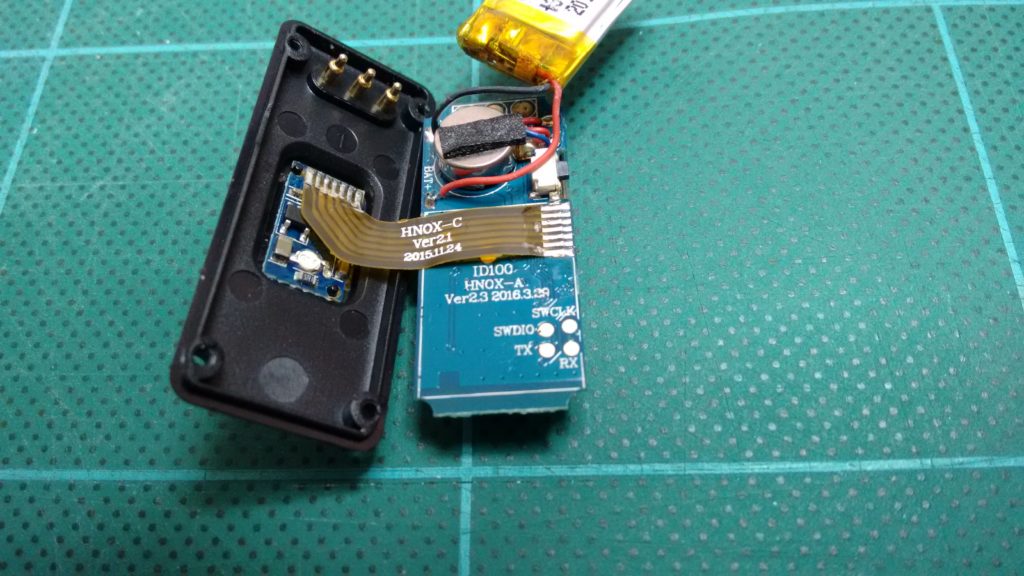
These watches can be programmed by soldering directly to the SWDIO, SWCLK and GND pins. You can also connect to the TX and RX pins for debugging.
The T28 and ID107HR Plus do not label these pads by silkscreen so please see ID107HR Plus pads,  ,
,  for these pins.
The ID107HR+ UART Tx,Rx were chosen to be on p23,p24 because the pads are next to the programming pins.
The T28 UART Tx,Rx were chosen to be on p26,p25 as their pads are near the OLED ribbon.
Progamming is via a SWD programmer (J-Link, ST-Link etc.) using sandeep's core.
- Download and install the Arduino IDE (At least v1.6.12)
- Start the Arduino IDE
- Go into Preferences
- Install the board package(s)
4.1 (If you havent already done so) Install @sandeepmistry's nRF5 core arduino-nRF5
4.2 Add
https://sandeepmistry.github.io/arduino-nRF5/package_nRF5_boards_index.jsonas an "Additional Board Manager URL" 4.3 Install arduino-nRF5-smartwatches 4.4 Addhttps://micooke.github.io/package_nRF5_smartwatches_index.jsonas an "Additional Board Manager URL" - Open the Boards Manager from the Tools -> Board menu and install "Nordic Semiconductor nRF5 Smartwatches"
- Select your nRF5 smartwatch from the Tools -> Board menu
The nRF52 based T28 is quite different. Its pin allocation table is located here @fanoush has done a great job on getting the DS-D6 pin allocation. It is hosted here
| peripheral type | name | pin | IDO003 | ID100HR | ID107HR | ID107HR Plus |
|---|---|---|---|---|---|---|
| accelerometer | Kx022 | SCL | 14 | 14 | 14 | 5 |
| SDA | 16 | 16 | 16 | 3 | ||
| INT | --- | --- | --- | 6 | ||
| ADDR | --- | --- | --- | 4 | ||
| NCS | --- | --- | --- | 7 | ||
| optical HR sensor | Si1143 | SCL | --- | 26 | 22 | 18 |
| SDA | --- | 28 | 23 | 10 | ||
| INT | --- | --- | 24 | 8 | ||
| LED | --- | --- | --- | 9 | ||
| SPI flash memory | MX25L | MISO | --- | --- | --- | 27 |
| MOSI | --- | --- | --- | 31 | ||
| SCK | --- | --- | --- | 30 | ||
| CE | --- | --- | --- | 28 | ||
| side tactile button | --- | BUTTON1 | 4 | 4 | 4 | --- |
| capacitive touch button | RH6015C | BUTTON2 | 4 | 7 | 7 | ? |
| capacitive touch screen | IQS263 | --- | --- | --- | --- | ? |
| vibrate motor | --- | VIBRATE -or- | 7 | 8 | 6 | ? |
| LED_BUILTIN | ||||||
| serial UART | --- | Tx | 18 | 18 | 18 | 23 |
| Rx | 17 | 17 | 17 | 24 | ||
| OLED | --- | MISO | 31 | 3 | 3 | ? |
| --- | MOSI | 29 | 2 | 2 | ? | |
| --- | SCK | 30 | 1 | 1 | ? | |
| --- | RST | 1 | 30 | 30 | ? | |
| --- | CS | 2 | 29 | 29 | ? | |
| --- | DC | 0 | 0 | 0 | ? | |
| battery voltage level | --- | --- | ? | ? | * | ? |
- --- : not applicable
- ? : unknown
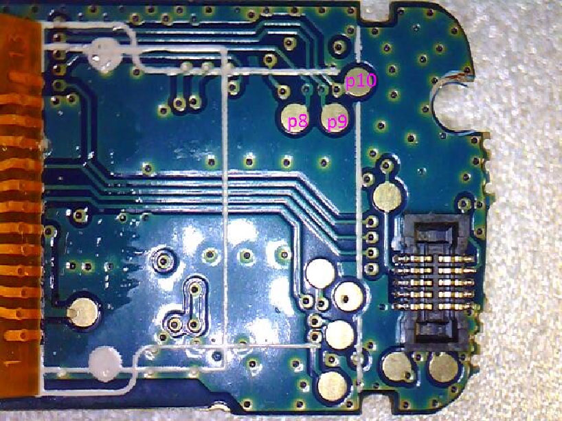
- * : unknown (easily found - perform an analog read on each pin), but AIN{0:7} = p{28,27,1,2,3,4,9,10} so it must be one of p9,p10,p27,p28
- 0x1F : Accelerometer (Kx022/Kx023)
- 0x5A : Heart Rate Sensor / PPG (Si1143)
- 0x76 : Altitude / Pressure / Temperature (HP203B)
- nRF5 core is written and maintained by Sandeep Mistry
- Support for these smartwatches originate from Roger's arduino-nRF5-customised repo
- ID100HR picture is from Roger, embedded on his website article
- (Modified) IDO003 picture is from Gordon, embedded in this conversation
- ID107HR picture is my own
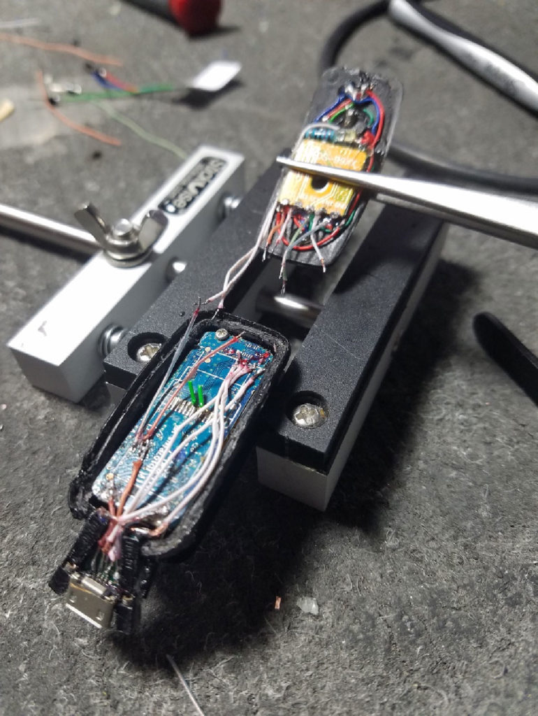
- ID107HR Plus picture is from Curt, embedded on Roger's website article
- (Modified) ID107HR Plus pads is from Curt, embedded on Roger's website article
- DS-D6 from @fanoush