Welcome back BLE enthusiasts, to the 3rd installment in Punch Through’s ‘Maximizing BLE Throughput’ blog post series. BLE 5’s Data Length Extensions are one of the largest performance improvements ever made to the BLE specification. Here’s how you can take advantage of Data Length Extensions to achieve 50 KB/s of throughput while consuming less power. It’s even supported by iOS and Android devices
Update: Please check out our other blog posts in the Maximizing BLE Throughput series. You can find a lot of great information to better understand how BLE works and what factors affect transfer speed, DLE, etc. But be aware that some of the information in these posts may be outdated.
Part 1: Maximizing BLE Throughput on iOS and Android
Part 2: Maximizing BLE Throughput: Use Larger ATT MTU
Part 4: Maximizing BLE Throughput: Everything You Need to Know
Data Length Extension
As you’ve probably heard, read, or frustratingly experienced first-hand during a 20-minute long firmware update of your device, BLE was not initially designed for high-throughput applications and use cases. However, BLE quickly became the go-to means of communication between mobile devices and connected products of all types and use cases. Best practices and ways to squeeze as much performance out of BLE as possible existed, but there was only so much developers can do with the protocol. For years, slow data throughput remained the bane of many BLE developers and their products.
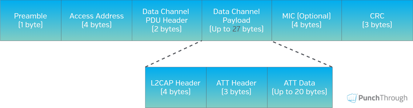
Thankfully, the Bluetooth Special Interest Group (SIG) addressed this in the Bluetooth 4.2 Core Specification release by introducing Data Length Extension (DLE). DLE is a feature added to the Link Layer that allows the Data Channel Protocol Data Unit (PDU) Payload field to be increased from the default 27 bytes to up to 251 bytes, as shown in Figures 1 and 2 below. Each Link Layer packet has 14 bytes of “overhead”: a 1-byte Preamble, a 4-byte Access Address, a 2-byte Data Channel PDU Header, a 4-byte Message Integrity Check (MIC), and a 3-byte Cyclic Redundancy Check (CRC). The MIC field is shown as optional because it is only used if encryption is enabled.
Bluetooth 4.0/4.1 Link Layer Packet Structure
Bluetooth 4.2/5.0 Link Layer Packet Structure

Notice the only difference between Figure 1 and Figure 2 is the increased Data Channel Payload size, which therefore means an increased ATT Data size. However, it is important to note that DLE can be supported to varying degrees; it is not an all or nothing feature. For instance, a device with DLE capability can support a Max Data Channel Payload size anywhere between 27-251 bytes and those values can also vary depending on the direction of the data (i.e., asymmetrical support).
How to Enable DLE
How you’ll actually enable DLE in your project or application will depend on the chip, stack and SDK you’re running on, but at a lower level, the following needs to happen:
- Both the master and the slave must support the Bluetooth 4.2 specification or newer (see the LL_VERSION_IND exchange)
- Both the master and the slave must support the LE Data Packet Length Extension Link Layer feature (see the LL_FEATURE_REQ and LL_FEATURE_RSP exchange)
- Either master or slave must initiate the actual Data Length Update Procedure by sending an LL_LENGTH_REQ command, which must be responded to with an LL_LENGTH_RSP command to complete the procedure. The following four values are negotiated between the master and slave during the Data Length Update Procedure:
- connMaxTxOctets – the max number of payload bytes/octets that the stack can send in a single link layer data packet
- connMaxTxTime – the length of time in microseconds that the stack can be actively transmitting a single link layer data packet
- connMaxRxOctets- the max number of payload bytes/octets that the stack can receive in a single link layer data packet
- connMaxRxTime- the length of time in microseconds that the stack can be actively receiving a single link layer data packet
After the Data Length Update Procedure, both master and slave determine their own set of maximum commonly supported values for outgoing and incoming data. Here’s a visual illustration of what the Data Length Update Procedure looks like:
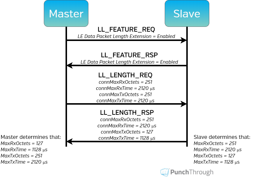
In the example depicted in Figure 3, the master initiates the Link Layer Feature Request (LL_FEATURE_REQ) since it supports the LE Data Packet Length Extension feature (among others) and wants to know if the slave does as well. The slave responds with a Link Layer Feature Response (LL_FEATURE_RSP) command to inform the master of all of the Link Layer features it supports, including LE Data Packet Length Extension. Now that the master knows the slave has DLE capability, it’s time to determine exactly the max Data Channel Payload sizes this connection can use. According to the LL_LENGTH_REQ, the master supports DLE to the full 251 bytes in both directions. However, the slave’s LL_LENGTH_RSP indicates it supports receiving a full 251-byte Data Channel Payload, but can only transmit Data Channel Payloads of 127 bytes. Lastly, using those values, both master and slave determine how many bytes of Data Channel Payload they can send and receive.
Therefore, a connection event in which both master and slave send a Max Payload Data Packet would look like Figure 4 below from the perspective of the slave.

NOTE: The connMaxTxTime and connMaxRxTime values are typically calculated by the size in bits of the largest possible Link Layer Data Channel packet, including overhead, at the LE 1M PHY data rate. For example, when the connMaxTxOctets value is 251 bytes plus the standard 14-byte overhead for the Link Layer packet, the connMaxTxTime = (251 + 14 bytes) * 8 bits * 1 μs = 2120 μs.
Benefits of DLE
So now that we’ve broken down how Data Length Extension can be enabled, let’s discuss the benefits it provides. Most obviously, DLE increases the amount of payload in a single link layer packet from 27 to 251 bytes, almost 10x more data than before. “So that would mean the max throughput should be ~10x better with DLE, right?”

Not entirely, and this is where things get a little complicated! If connections were always limited to a single transmission from both the master and the slave (i.e., a TX/RX pair) per connection event, then sure, we would see ~10x throughput improvement. However, we know we can have multiple TX/RX pairs per connection event. Before the addition of DLE, it was somewhat common to think of the amount of data that could be sent as the max number of packets or TX/RX pairs per Connection Event (like we did back in Part 1 of this blog series). However, now that DLE allows for Data Channel Payload sizes to be vastly different, that term does not universally apply anymore.
Instead, the amount of data transmitted in a single connection event is generally limited by the amount of time that both the master and slave radios are allocated to transmit and receive data (sometimes referred to as the Connection Event Length or Connection Event Duration). The Connection Event Length cannot be longer than the Connection Interval itself but is otherwise nebulous since it is not negotiated between master and slave, and its value will depend on a multitude of things, which we won’t attempt to explain in this post. For most products, however, the Connection Event Length will be as long as the master chooses to allocate radio time for because the master (usually a smartphone) has other connections to service and more tasks to run.
To help visualize and understand the Connection Event Length concept better, let’s look at and compare a single connection event from a connection with full DLE support (Figure 5) vs. one with no DLE capability (Figure 6). For simplicity’s sake, let’s assume data transfer is unidirectional from the master to the slave, as in the common use case of an Over-the-Air (OTA) firmware upgrade of a peripheral device. Let’s also assume that the Connection Event Length is 5 ms in both connections. Because we are only focusing on the differences of a single connection event for this example, the connection interval is essentially irrelevant.

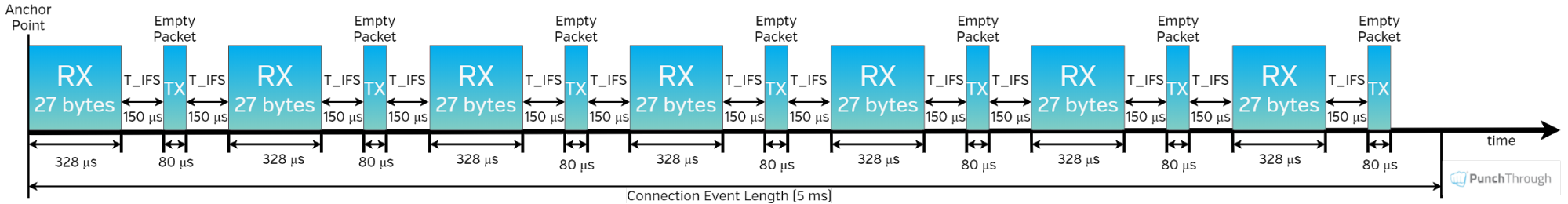
In Figure 5, DLE is fully supported with a Max Data Channel Payload size of 251 bytes. In Figure 6 however, DLE is not supported so the Max Data Channel Payload size is the default 27 bytes. Now let’s calculate and compare the amount of data transferred in both cases (assuming that every packet is an L2CAP Start packet). In the DLE-enabled connection, there are two 251-byte packets, each with 7 bytes of overhead (L2CAP & ATT headers) for a total of 488 bytes of ATT data. In the connection without DLE, there are seven 27-byte packets. Subtract the same L2CAP and ATT headers from each packet and we’re left with 140 bytes of ATT data. So in this example, using DLE gives us a ~3.5x improvement in ATT data throughput (488/140 = 3.48).
So, even though DLE does not automatically equate to a 10x improvement in throughput, it does allow for a much higher percentage of the total Connection Event Length to be spent on transmitting Data Channel Payload by reducing overhead in the following ways:
- Higher ratio of data to overhead in Link Layer packets – By increasing the size of the Data Channel Payload from 27 to 251 bytes while the Link Layer packet overhead remains constant at 14 bytes, the ratio of time spent transmitting data vs. overhead is much higher.
- Less Inter Frame Space time – The Inter Frame Space (IFS) is a standard 150 microsecond time interval (T_IFS) in which the radio is inactive while switching from transmitting to receiving (and vice versa). By increasing the number of payload bytes per transmission via DLE, you can send data in fewer transmissions, which results in fewer inter frame space delays. Notice how much more time is spent transitioning the radio between modes (empty white space) in Figure 6 compared to Figure 5.
- Fewer empty packets – When data is only being sent in one direction at a given time, using DLE will result in less wasted time sending empty packets from the side not currently sending data. In the above example of a FW update which only transmits data from master to slave, with DLE enabled there are only 2 empty packets that need to be transmitted from slave to master vs. 7 empty packets without DLE.
Another benefit to having less overhead is less time spent actively transmitting and receiving, and therefore lower power consumption. In short, using DLE provides both faster throughput and longer battery life.
Max Throughput Results with DLE
“Okay, get to the point. What exactly is the max throughput for a BLE connection?” Well… the maximum achievable throughput values will vary depending upon many different factors: hardware/chipset, PHY layer used, stack version, OS version, direction of data, how busy the master or slave devices are with other connections and tasks, wireless environment, etc. We can say with certainty based on our own testing that ~50 KB/s data throughput is achievable on newer Android and iOS devices with DLE enabled on the default LE 1M PHY.
Thanks for reading!
Table of Acronyms Used
| ATT | Attribute Protocol |
| BLE | Bluetooth Low Energy |
| CRC | Cyclic Redundancy Check |
| DLE | Data Length Extension |
| GATT | Generic Attribute Profile |
| IFS | Inter Frame Space |
| L2CAP | Link-Layer Control and Adaptation Protocol |
| LE 1M (or 2M) PHY | Low Energy 1 (or 2) Mbps Data Rate Physical Layer |
| LL | Link Layer |
| MIC | Message Integrity Check |
| MTU | Maximum Transmission Units |
| OS | Operating System |
| OTA | Over-the-Air |
| PDU | Protocol Data Unit |
| T_IFS | Timing of the Inter Frame Space (150 μs) |