- Home
- Product Categories
- WiFi
- SparkFun WiFi Shield - ESP8266

SparkFun WiFi Shield - ESP8266
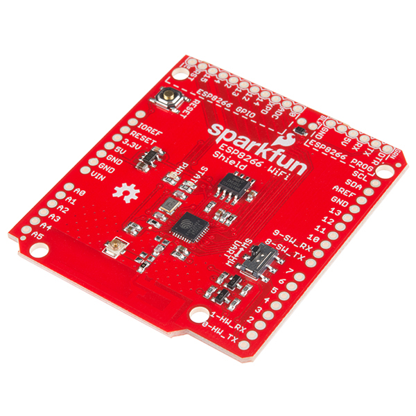
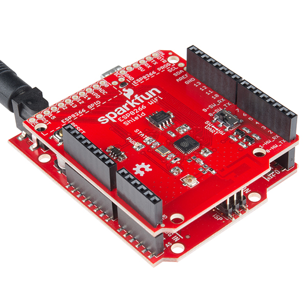
The SparkFun ESP8266 WiFi Shield is an Arduino compatible shield for the ESP8266 WiFi SoC – a leading platform for Internet of Things (IoT) or WiFi-related projects. There are a variety of designs based around the ESP8266, including tiny, modular boards and more accessible development boards like our very own SparkFun ESP8266 Thing. The ESP8266 WiFi Shield finds a middle ground between the Module and the Thing that provides a great introduction to the ESP8266 – without leaving the comfortable hardware confines of your Arduino. If you just have an Arduino project that needs an inexpensive gateway to the Internet, the ESP8266 WiFi Shield does everything from turning on an LED to posting data online to a data streaming service.
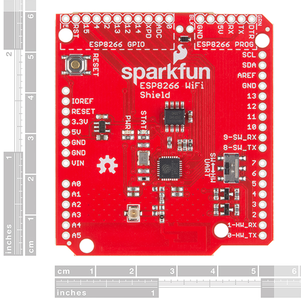
The ESP8266 WiFi Shield comes pre-flashed with an AT-command firmware, so it can be controlled by any UART, but it also breaks out and provides command access to all of the ESP8266’s I/O. Since this is an Arduino shield, it makes it easy to attach to any development board that utilizes the Arduino R3 layout. All it will take is a little soldering to attach the necessary headers. The ESP8266 is much more than a simple serial-to-WiFi gateway. It has almost a dozen I/O that can be configured as digital inputs or outputs – it even has an ADC! These GPIO are all broken out towards the top-left side of the shield. Additionally, the ESP8266 WiFi Shield can be repurposed and reprogrammed through the programming port found on the top-right side of the shield. Whether you want to add AT commands of your own, or flash custom firmware on the ESP8266, this port may come in very handy especially with it utilizing the pinout of our FTDI Basic breakouts.
This shield comes populated with all components as shown in the images and schematic; but it does not come with headers installed. We recommend the Arduino R3 Stackable Header Kit.
- Arduino R3 Layout
- 802.11 b/g/n
- Wi-Fi Direct (P2P), soft-AP
- Integrated TCP/IP protocol stack
- Integrated TR switch, balun, LNA, power amplifier and matching network
- Integrated PLLs, regulators, DCXO and power management units
- Integrated low power 32-bit CPU could be used as application processor
- +19.5dBm output power in 802.11b mode
- Schematic
- Eagle Files
- Hookup Guide
- AT Command Set
- GitHub (Design Files)
- GitHub (AT Arduino Library)
- Product Video
SparkFun WiFi Shield - ESP8266 Product Help and Resources
ESP8266 WiFi Shield Hookup Guide
July 16, 2015
Interface your Arduino with an ESP8266 to give it inexpensive access to your WiFi network and the Internet!
Internet of Things Experiment Guide
November 23, 2016
The SparkFun ESP8266 Thing Dev Board is a powerful development platform that lets you connect your hardware projects to the Internet. In this guide, we show you how to combine some simple components to remotely log temperature data, send yourself texts and control lights from afar.
ESP8266 Powered Propane Poofer
March 15, 2016
Learn how Nick Poole built a WiFi controlled fire-cannon using the ESP8266 Thing Dev Board!
How do I connect an external antenna?
If you want to switch from the internal trace antenna to the U.FL antenna connector, a zero ohm resistor needs moved. This picture shows how to do that! :-)
**ESP8266_Shield_SoftSer and Blynk**
ESP8266_Shield_SoftSer does work with Blynk. Customer pointed out that you need to change RX/TX from 2,3 to 8,9 and it will work.
http://community.blynk.cc/t/uno-with-sparkfuns-esp8266-shield/1612/8
Core Skill: Soldering
This skill defines how difficult the soldering is on a particular product. It might be a couple simple solder joints, or require special reflow tools.
Skill Level: Noob - Some basic soldering is required, but it is limited to a just a few pins, basic through-hole soldering, and couple (if any) polarized components. A basic soldering iron is all you should need.
See all skill levels
Core Skill: Programming
If a board needs code or communicates somehow, you're going to need to know how to program or interface with it. The programming skill is all about communication and code.
Skill Level: Rookie - You will need a better fundamental understand of what code is, and how it works. You will be using beginner-level software and development tools like Arduino. You will be dealing directly with code, but numerous examples and libraries are available. Sensors or shields will communicate with serial or TTL.
See all skill levels
Core Skill: Electrical Prototyping
If it requires power, you need to know how much, what all the pins do, and how to hook it up. You may need to reference datasheets, schematics, and know the ins and outs of electronics.
Skill Level: Rookie - You may be required to know a bit more about the component, such as orientation, or how to hook it up, in addition to power requirements. You will need to understand polarized components.
See all skill levels
Comments
Looking for answers to technical questions?
We welcome your comments and suggestions below. However, if you are looking for solutions to technical questions please see our Technical Assistance page.
Customer Reviews
3.1 out of 5
Based on 35 ratings:
3 of 3 found this helpful:
Works great
If you want an easy and cheap way to give your arduino WiFi capabilities, this is the best way to do it. Just solder on the headers, fit it on your arduino, and you're good to go. I would recommend buying a u.fl antenna however, as the strength of the board isnt that great by itself. Fortunately sparkfun sells the WRL-11320 which snaps right on to this board. Another thing to note is that if you need SSL, the ESP8266 does not have that capacity, so no HTTPS. Otherwise though, this product is a breeze to use, works perfectly, and all at a great price.
1 of 1 found this helpful:
Using with the pubsubclient library
Wireless works fine, but...has anybody got this working with the pubsubclient arduino library? For me it just hangs when I try to connect with the client.connect. I can't figure it out...
Does anybody know if there's a different library that I should be using?
1 of 1 found this helpful:
Works Great: Awesome Possibilities!
No problems. Started working and learning from the connection guide. The demo code compiled and works great! I can't say enough good things about the SparkFun Hookup guides. By providing those excellent examples of functionality, they allow me to envision a technically feasible path toward my goals.
Using the SparkFun RedBoard and the 2.4GHz antenna (because the underground lair is so far from the router).
1 of 1 found this helpful:
Necessary thing in my collection
Having the breakout pins and compatibility with arduino headers helped a lil. Having SPI breakout would be better for hackers. However, I liked it much. ESP8266 201 also would have done good to me
1 of 1 found this helpful:
Unreliable/Broken
Either I'm incredibly unlucky and got two duds, my Arduino Uno is broken in weird ways or this thing is just unreliable. Essentially, this shield has two states of failure: If I pull it out a little from the Arduino sockets, it blinks the blue light a bunch, and then reports that it failed to establish a connection. If I push the shield all the way in, the red LED is the only thing that lights up, and the ESP8266 chip gets awfully hot. The board then fails to initialise.
Since the second failure condition sounds an awful lot like a short circuit, I RMA'd it, but the second board I got exhibits the same behaviour. I've also noticed that the pads on the broken out ESP8266 pins touch the Arduino Uno USB connector when pushed in all the way, which might short it, but the short-circuit like behaviour also occurs even if the pads don't touch it, so something's weird.
Either way, buyer's beware - I've yet to actually successfully use this thing.
Sorry to hear that. It seems odd that they would both fail in the same manner. You’re right that these pins might be shorting onto your USB port. A dab of nail polish on the USB casing, or a bit of electrical tape can help to isolate the USB housing from shields on top. I will suggest that we move those pins in the future to avoid making contact. I know you contacted our tech support team for your RMA, but maybe reach out to them again, and see if they recognize this behavior, and how to fix it. (They're really good!)
2 of 2 found this helpful:
Getting into IoT in One Morning
I was connected to the internet and posting data within a couple of hours. Look, no internet-connected project is going to be a walk in the park, especially the first time around. Going from the relatively simple realm of the Arduino IDE to the relatively not simple realm of networking, and then trying to cobble the two together, is a big leap.
I've had no problems; this little shield did exactly what I hoped. Even soldering on the headers (this was my first time!) wasn't too bad. And for $15? Love it!
1 of 3 found this helpful:
Haven't connected to a network yet
I have tried unsuccessfully now to connect to any of my wireless networks using the shield and the accompanying documentation. Every example has ended in error. I have tried various forms of authentication and cannot even get connected to an unsecured network. All return the error code - not a timeout.
The code in the Hookup guide should be operational. We have some issues with connecting to our office wifi because of router settings holding us back. When mine doesn't connect I get a Error code as well, not a timeout. However, when attempted at home, we can get these to connect.
For those frustrated with this product
It could be a five but belongs a three.
Save yourself a lot of headaches and add a second row of double pins. Simple. I had every problem encountered below solved by adding the second row of pins. The physical layout is awkward. My serial was set to HW. Move to SS.
No "hello world" example? Well yes but not obvious. Start with the ping demo. Set sid and pw. Next demo. Install fing and scan your network and ports. That should be in every "citizen scientists" toolbox.
Unreliable
Loaded up the Shield Demo Sketch on my Arduino Uno R3. Shield is only discovered one out of every 5 or 6 times. Have to hit the reset button a couple of times. Anyone else have this problem ? Help !!
Sorry you're having trouble with the shield. I would recommend contacting our tech support team at techsupport@sparkfun.com, to see if they can help resolve the issue.
0 of 2 found this helpful:
Cant connect to Wifi
Just wont connect to the Wifi. Magically happened once and thats it. Will experiment with it further, but not very optimistic....
Nice tool with great supporting "how to"
The video support for this was instrumental in all steps in getting this to work for me. I am a medium novice at Arduino and related activities. I was able to brush up on tips for soldering so I could connect the pins without too much trouble. Getting the IP address to recognize my device, but the tutorial gave me the confidence to stick with it until it connected. I'll be looking forward to posting data "live" with my next project.
DOA
I'm sure this shield is nice to work with but mine was DOA. Board is pulling a huge amount of current and the ESP8266 chip is so hot is it burns to touch. I assume the ground plan underneath the QFN package is shorting something. Intermittent IDE connection that is easily resolved if I don't have the shield placed (in sw mode). I'll pull the chip off at work and try to reflow it but tempted to through it in the trash.
Improve your quality control! There is a hole in your quality check that allowed a dead board to be shipped to a customer.
Sorry to hear you've had issues with the board. If you contact our tech support team, they can help you to resolve any issues.
Incompatibilities and Redboard flash usage
I bought the ESP8266 shield to replace the XBee system I was using on my old weather station outdoor components. The stack was going to be RedBoard -> ESP8266 shield -> Weather Shield -> instruments. Unfortunately, when I loaded the ESP8266 AT library and the weather station libraries I only had 32 bytes of flash remaining on the Redboard - not enough to initiate an MQTT session to send weather data or even a raw TCP socket to send to a custom server on the local network. So, need more memory = upgrade to a Mega 2560, right? Well, the Mega (either clones or the genuine Mega 2560 boards) can't recognize the ESP8266 shield no matter what I do. To solve this problem and get my weather collection up and running I used a genuine Mega 2560, an Adafruit WINC1500 WiFi breakout (SPI device), and the SparkFun weather shield. I then used the Adafruit MQTT library to send data to my MQTT broker that I have running on my network.
So I ended up with an extra ESP8266 shield and Redboard. I'm sure I can find something to do with it, but I'm disappointed that the configuration I planned on won't work. So minus two stars for R3 board incompatibility.
If you're playing with ESP8266, GET THIS SHIELD :^)
This product has been a real time saver and partner in my efforts with the ESP8266! Everything is broken out, easy to access and modify. The Tutorial is also GREAT and the sample code included with it makes a great jumping off point for first time or expanded development. I've bought four already and will be getting more. I'd give this item a full FIVE start rating if it came with the headers (why doesn't it?) and if the antenna selection were switch selectable or the SMD resistors were the next size up for beginning solderers/hobbyists.
Doesn't implement the standard Client.h interface. PubSubClient lib won't work.
Don't bother trying to use this for your IoT project -- the library doesn't implement a standard Client.h interface. I tried to use the MQTT PubSubClient library that I've used before with the wired Ethernet shields, but the library seems to be looking for null terminated strings, which the Client.h interface doesn't have. You can connect to your MQTT Broker just fine, but you will never 'publish' any IoT data, as it can't get through the interface correctly. https://github.com/knolleary/pubsubclient/issues/107
Had bad luck I guess
This WIFI shield unit was very very sensitive to the degree it was inserted into the mating connectors on the Arduino Uno. When inserted fully the WIFI chips ran very hot and it would not function. I got the shield to function only one time by fiddling with very light insertion of the pins. SF Support sent me a replacement board, but it only acted dead all the time. I tried using two different Arduino UNOs which still function fine with other shields. I gave up on using this WIFI design and am waiting for SF support to tell me if I can return both units for a refund.
Easy to use, works great
I just got this in the mail last night and had the headers soldered and the board up-and-running with the sample code in about 30 minutes.
I also purchased the 2.4GHz Antenna (WRL-11320) for improved connectivity and range as another reviewer suggested. I highly recommend buying the antenna (it's only $4.95) and super easy to install - it just snaps into place.
Much better than trying to use the bare bones ESP8266
I struggled to integrate ESP8266 modules with projects in the past. They are notoriously temperamental and fragile. The SparkFun shield makes things much easier. The only gotchyas were that some of the example sketches needed tweaking to get to work with some web sites like those hosted on Heroku... but that is not a hardware issue. This is a great little module and a nice price.
Should be discontinued..
I have to say I’m very disappointed with the ESP8266 WiFi Shield you guys are selling. I am pairing this up with a SparkFun RedBoard and even with using the examples to connect to 2 different consumer level access points I’m getting very crappy results. The shield most of the time fails to establish a connection to the RedBoard.
I have tried 2 different shields, 2 different RedBoards, internal antenna, re-positioned the 0-ohm resistor and purchased/tried an external antenna.. Have also created 3” jumper wires to keep the shield a couple inches away from the RedBoardto eliminate an interference condition.. and still it’s very erratic initializing the shield, connecting to the AP, or establishing a stable enough connection to communicate longer than a second or so.
I’m within 8ft of the access points. I have tried a linksys wireless-n, and asus wireless-n. Tried different levels of encryption. Regardless I needed to play the reset game until a connection happens, then it will drop out and not function until I play the game again.
I have been a big fan of sparkfun and have spent a decent amount of money with you guys over the years.. but I have to say this product is garbage.
Extremely finicky
After ordering four of these and experiencing the same issue with each of them, I'm not sure I'd use these again. When hooked up to USB power, they functioned flawlessly. On battery power in a real circuit, no combination of filtering capacitors could prevent them from rebooting randomly. Maybe in a circuit with extremely clean power they'd have fared better, but I ultimately had to scrap using them in favor of another ESP8266 board that didn't suffer from the same issues.
Hello!
Sorry to hear about the issues with the ESP8266 shields. Have you reached out to our technical support department @ Techsupport@sparkfun.com? The can help to resolve issues with the shields.
Not recommended for Mega
I bought this board specifically for use with an Arduino Mega IoT project. I did some initial tests using an Arduino UNO, which worked fine. I then connected it the the Mega and got.....nothing. After a lot of experimentation and Googling, I find that several people have confirmed the board does not work with the Mega.
As an aside, all such shields should come with a full compliment of headers, especially when you pay extra for them as I did. Luckily I had some spares that I could cut up to get the needed SCL & SDA pins.
Not recommended.
Yeah, unfortunately in this situation, the board was designed with the redboard in mind, so it will not work right out of the box plug and play for the Mega and our example. We have also seen the board be shorted by the USB-B connector on the board, so you might consider trying to re seat the board a little higher up off the connector, or add an insulating pad like some electrical tape between the two devices.
On my second one, wish I had never come across it
Produces a different response every time I reboot the UNO it is plugged into. Sometimes it works, sometimes it doesn't. Mostly it doesn't. The first one I bought bricked out for no apparent reason. Attempts to flash it are extraordinarily difficult and produce near-random results, after many hours spent dredging into the internet trying to find .bin files, flash software that actually functions, addresses, etc. I'm getting the picture about Arduino - you basically spend a lot of time trying to fix other people's products. It isn't fun, it isn't clever. It is just a waste of time.
Hello!
You can reach out to our technical support department here: https://www.sparkfun.com/technical_assistance I am sure they would be happy to assist you to the best of their abilities.
Seems to be a solid performer but not fast
I'm using the ESP8266 wifi shield to dish up less than 600 bytes of json per request. The ESP8266 is easy to configure and communicate with and behaves consistently. I have an IFU to RP-SMA cable connected to a 2.4GHz duck antenna. I'm using it with a Mega 2560, so I had to wire Mega pins 52/53 to 8/9; tested on an Uno R3 and worked without any jumpers. I have two issues, 1) best speed is under 600bytes/sec, 2) can't seem to use any other port than 80 but haven't done a deep dive either on the code. Other than that, it seems to be a solid performer for under $15.
Couldn't flash it
Comes without the head pins and I wasn't able to flash it with the firmata wi-fi code, so it's unusable for me...
Works like a charm!
I bought this with some stackable headers. It was extremely easy to solder the headers on and fit the shield onto my Arduino Uno. The library on GitHub was very easy to use as well. Great examples that got me up and running in no time flat!
Works great
Works great, but wish I could assign a static IP to it. Using it with an Arduino UNO and some temperature sensors. Not using phant.io.
problems
Unfortunately, my board arrived DOA, which I discovered after a weeks worth of trying to breath life into it. Sparkfun has experienced similar difficulties with other boards of this class, and has been wonderful about addressing this and other issues. I'll await their resolution of problems here, as I know they will. I buy often from them and will continue to do so. Stuff happens even to the best and I wouldn't give the company itself bad reviews over a production issue. Hope it gets fixed soon.
Not working
I need to re-flash the AT commands to the hardware. Tech support has not been totally helpful so that I can re flash.
Sorry to hear that! The original firmware can be found in this Github repository. you will need to obtain the Espressif flash utility to upload the firmware to the board.
Our Sensor Server Connection
After soldering the headers, it worked out of the box using the demo sketch. My granddaughter and I are using this with a Sparkfun Arduino Blackboard and software serial. We are also using an external antenna. I don't anticipate any problems using it to connect sensor servers to a Raspberry Pi client. The most difficult part will be figuring out some of the library calls that we will need. The sources are the AT command doc and the library code itself that is not well commented. I still gave it five stars because it is an elegant package with a nice on-board command set. After some research, I got it to work as a server using the demo code that I developed at https://github.com/votsek/ESP8266-WiFi-Demo. I purchased three and all work fine. Another note: they all have a unique MAC, which may be important for some applications.
Can't get it to work reliably with a Mega2560
October 2015 revision: after fighting this board for a long time, I have to admit defeat. I can't seem to get the board to function reliably. I get init failed (board unresponsive to AT command), connected as 0.0.0.0, connected as 254.255.255.255, and connection to server failed, then the occasional times when it works fine. I've looked at the library code and it seems reasonable, yet the board just behaves unreliably for me (connected to the hw serial of a Mega 2560). I wonder whether there's just something about it that doesn't work with a Mega vs an Uno.
....my original review...
On the plus side, hey, it's a $15 WiFi shield, and hooking it up is pretty simple! On the minus side, mine fails to communicate if I seat the board snugly against an Arduino Uno or Mega; I have to seat it, then pull it out a tiny bit. I suspect the programming pins are shorting against the grounded case of the USB A connector on the Arduino. Also on the minus side, the provided library makes the app provide housekeeping code to filter out the ESP8266 protocol (+IPD,0,1470: etc.) from received data.
Other than that I'm having fun with the board, and am looking forward to using it in a Lunar Clock project I'm putting together.
Hi, You're right that these pins might be shorting onto your USB port. A dab of nail polish on the USB casing, or a bit of electrical tape can help to isolate the USB housing from shields on top. I will suggest that we move those pins in the future to avoid making contact. Thanks
Replaced a CC3000 - No more timeouts!
I had a project with a CC3000 and multiple times a day it would hang. I worked around this by adding a WDT to reset it when it would hang, but this caused some issues with my projects display. I took half a day to retrofit with the ESP8266 shield and now have run for 24 hours without any hangs . . . and at half the cost!
Hardware probably fine but can't run it.
I have been unable to install the software for the wifi board in arduino despite your tech support guys best efforts. It seems like the arduino must be buggy In the boArd manager area.
great product. tutorial could be improved
I got this in the mail and it took me a bit of time to get it working. There was nothing wrong with the board and getting Ping working wasn't too hard but if anything goes wrong there isn't much info as to what. My workshop doesn't have super strong WiFi signal strength but I didn't know if that was the problem. I finally set up a Kindle hotspot right next to the board and it worked. Still haven't gotten the server sketch to work but it's just a matter of time and debugging. But the functionality is impressive and the Arduino environment makes it easy.
works ok, finicky shield headers
Spark ESP8266 Shield demo works ok. I tested signal reception in next room -- okay. Problem with finicky headers. Found that it was best to insert pins just a little bit -- if I pushed them all the way in got "error communicating to board."
Retired Electronic Tech.....
......working with new IoT projects.
---------- Tech Support Tips/Troubleshooting/Common Issues ----------
If there are no visible shorts on the board, it could be the way that the shield's header pins are connected to the Arduino. Try to not jam the whole board into the Arduino and connecting the board level with the microcontroller. You might see this error in the serial monitor when running the ESP8266_Shield_Demo.ino sketch example code:
During a few instances, the board would work again when I pulled the known good ESP8266 shield off the Arduino and restacked it so that the shield is level.
Connecting with an Arduino Mega?
You can also see this error if you are using the example code with the Arduino Mega. Unfortunately, the Arduino Mega has limitations on certain pins and the Rx on pin 9 of the Mega will not work with software serial.If you are using software serial [ https://www.arduino.cc/en/Reference/SoftwareSerial ] , you need to reroute the pins and redefine the software serial pins. The reason why is because not all the pins on the Arduino Mega 2560 can support change interrupts so only certain pins can be used for the Rx pin. Due to this limitation, you are not connecting properly to the ESP8266 Shield and therefore seeing this output error in the Arduino serial monitor.
Try looking at these two comments for alternatives and for an idea of how to reroute the software serial pins on your Arduino Mega => https://learn.sparkfun.com/tutorials/arduino-shields/discuss .
Why are you still selling this? The issue of instability and heating up at startup seems to happen to many users as you acknowledge. The forum has several threads on this going back 4 years. In all cases it is just closed with no resolution. You are doing a terrible disservice to your customers since you are wasting everybody's time when we have to spend hours trying to find a solution only to see that you know about this, have not made any fixes but still sell it as though nothing is wrong!!
The shield works...sort of, but the flash is entirely too small. 512KB makes it very difficult to flash other firmware variants on it sadly.
Check out the ESP32 WROOM Thing Plus.
Hello,
I purchase this product ESP8266 two week ago and it works fine with the example I can connect to the WiFi system of my home, but how is it possible to choose a host were i can put my data on. Because I want to use it with a temperature sensor and my tack is to show the temperature in a website or a webpage. Can anyone help?
Hello I bought this wifi shield to send sensor data to web server. I set LAMP in Raspberry pi and I use load cell to measure weight and arduino and raspberry pi is connected to wireless. And I downloaded library named sparkfun esp8266 AT library. Can I send weight that measured in arduino to web server if I use ESP8266-Phant Library? If I can't, How can I send weight to web server?
Does anybody know how many simultaneous sockets the ESP8266 can connect to? The WZ5100 can do 4 sockets for instance. It makes so when creating a web server, a socket won't lock up when needed.
I've had some luck so far getting this to work with my old Diecimila, thanks! Then I put it into "transparent transmission" (a.k.a. pass-through) mode with AT+SAVETRANSLINK, and now it won't respond to any AT commands. It just transmits whatever I say... is there any way to get it back out of pass-through mode? Or some kind of factory reset?
I am trying to connect to my home wifi. Its open w/ no password( Ive tried an empty string and a space in the password string.) When I run the demo here is what I get:
Press any key to begin.
ESP8266 Shield Present Mode set to station Connecting to Helds Error connecting Error: -3
Hi all,
I am using an ESP8266 to send a file from an Arduino DUE to a server using PHP. Basically, I read the data from the Serial and send 1000 bytes packages to the server. It works perfectly for any file that takes less than 2 minutes to send. I noticed that, independently of the size of the file, after 2 minutes the client.print() doesn´t work anymore. The server doesn´t return any error too. I thought it could be the timeout but timeouts are related to idle time... I am sending the data constantly.
Do you know anything about this issue? Thanks! :D - See more at: http://www.esp8266.com/viewtopic.php?f=32&t=10593&sid=52666a3fceea032bbabbdaea6cb9553f#sthash.zk2dQ3s4.dpuf
Can anyone give me some ballpark figures on the power draw I can expect from this in different modes when attached to an Arduino Uno? I've seen that it has a sleep and a deep sleep mode, though, this comment suggests that the deep sleep mode won't work due to the board's design.
I'm looking to power this from a 9V 109mA solar cell (hooked up to a Sunny Buddy with a battery), and I'm not quite sure whether I'm even close to having enough power. I'm still waiting for my Arduino Uno to arrive (since this doesn't fit my trusty Duemilanove) so I can't just trial and error this right now.
According to measurements on nurdspace.nl, the ESP8266's power draw during operation is close/beyond what the solar cell outputs, but since I don't plan on it continuously sending data, I'm hoping on it just scraping by.
Any suggestions on power conserving tricks for this are appreciated as well. If push comes to shove, I'll just hook up a second solar cell in series.
I ran out of memory and had to shift to a SAMD, any suggestions getting to work with the SAMD? I've tried switching the switch to HW on the shield but not luck
I have tried resetting and reprogramming but continue to receive the below message only. I made sure to leave the UART switch in the SW position. Using Genuino MEGA2560, power light is solid, and stat is blinking.
Error talking to ESP8266.
Error: 0
Looping forever.
I've tried this with two different routers based on other comments I read. I get the same Error with both routers.
UART communication in the MEGA2560 isn't via the same pins...duh
Please, could you sell this shield with already preassembled headers? I don't mind to pay a little more. Thanks!
That is surprisingly harder than it sounds. Our selective solder machine is great for soldering PTH parts and basically goes through and squirts solder on the PTH part. The thing is though that with the stackable headers that liquid solder drips down the male part of the headers which is a problem. Consequently for us to do stackable headers we have to solder them by hand, which gets time consuming. So, it isn't impossible for us to do, but I don't see us doing it happening anytime soon.
I would like to use this shield on a ChipKEY board (Arduino compatible running a 32 bit processor at 3.3V). Do you have a preferred path to take to get rid of of the level switching circuitry?
Cool! Unfortunately, there isn't a really easy way to bypass the level-shifting circuitry. I see two options:
which pins of the Arduino Uno does this shield use? I need 3 pwm pins, but it seems like there's a problems with the ones I'm using now
Is there any demo sketch for using this shield as an access point running a web server? I had no luck adapting the examples delivered with the SparkFunESP8266WiFi Library.
I received this today and soldered headers onto it. I plopped it onto an Arduino Uno (maybe this is my issue?) and plugged it in to try out the examples from the library. When I plug it in, it seems to kill off any existing wireless connections around... For instance, my home network goes down (laptop/phone both lose connections and can't find the network -- SSID disappears), and it seems to do the same with near by networks. Once I pull power from the Arduino, the networks pop back up and I can connect back to my home network again. Moreover, even with it plugged it, I upload an example and none can find the ESP8266. Any thoughts? Thanks!
Hi, I got this shield and the Sparkfun ESP8266 Thing a couple of days back, my interest is to use it for Machine-to-Machine using MQTT. There is quite a bit of support in the ESP8266 community for the Thing, and you can find quite a bit of sketches for MQTT on the Thing using ESP8266 library. However, I haven't found much on this Wifi Shield to plug-in MQTT support. Anyone having experience or familiarity with using this shield with MQTT please help. Thanks!
You should be able to use this shield with the pubsubclient MQTT Arduino library. There aren't any examples of using the library with an ESP8266 shield, but the basic example should be a straightforward port from the Ethernet library to the ESP8266 AT library.
As previously posted, I had no luck using the shield plugged into Arduino UNO R3s (but was able to use the shield on a Mega 2560 with some tweaks to the library).
Both of the UNO R3 boards I tried had DIP packaged ATmega328ps. I wonder if perhaps the shield was developed and tested with a Sparkfun Redboard (with SOIC MCU). Has anyone got the shield working plugged into a DIP package UNO? Perhaps there's too much electrical noise/EMI from a DIP packaged microcontroller?
As with every WiFi shield SparkFun starts selling, I must ask to those who have the experience, is this shield better in any way to the WiFly shield also sold by SparkFun? I use WiFly but I've been trying to find a shield with better support and documentation and can't afford to buy every one that comes out. Any comments?
This isn't bad for a first revision, but this design has a few nasty bugs that SparkFun should address:
For most MCUs, the reset pin is a high-impedance input. However, the ESP8266EX's reset pin sinks a crap ton of current when pulled down to ground (I don't remember if this is only the case when RESET is tied to XPD, or if it happens regardless). I design with the ESP8266EX SoC a lot, and I always put a FET on the reset pin to be able to pull it down. Definitely a nasty omission on SparkFun's part.
I really wish this board were designed with battery power in mind. SparkFun should have tied XPD_DCDC to the reset pin -- otherwise, you can't put the ESP8266 into deep sleep mode. It uses a ridiculous amount of current otherwise. I know that they've at least broken out the pin, but there's really no reason not to jumper it to reset -- users can cut the trace if they really need that extra GPIO input. And what's with the AP2112 regulator? It's got nasty-high quiescent current -- do you really need a 600mA regulator that's stable with 1uF of output capacitance to drive a 150mA part that you hung a 10uF off of it? Strange choice, but maybe that's all they have laying around?
Also, that PCB antenna shouldn't have any ground pour on the side (read TI's appnote), and those traces don't look like they're matched to 50R -- are those designed as microstrip or CPW? I wonder what kind of performance they're getting out of the RF section of that board.
Are there any SO-8 package regulators that are more appropriate and have the same pin-out as the AP2112k, so users could mod it? All I've found from a local store is the L4931, where sadly the "Enable" pin maps to an "Inhibit" pin.
Thanks Sparkfun for the wireless shield option for my Uno! Tried the board and it works using the example. Took a couple tries to connect but did finally. I connected to my garage router which is weak connection on my laptop. Thanks for the library and example. This is awesome! The ESP8266 opens up many possibilities for new boards.
Works as a "Thing" but gets flaky when stacked on an Arduino UNO R3. I tried plugging the shield into a genuine Arduino UNO R3 and an Inland (Microcenter) clone. In both cases I had to pull the esp8266 RST pin low for a second to get any sign of life from the shield. The shield's blue status light switches off after the first attempts to communicate with it (via sw serial pins 8 & 9).
I had more luck with a Mega 2560 board (Inland/Microcenter clone). Rather than cutting traces like Brad10 below, I set pins 8 & 9 as inputs and connected TX1(18) to 9 and RX1(19) to 8 with patch cables.
If you only have UNO boards, I'd suggest buying a "Thing" instead (until the next HW revision of the shield).
Changes to library to support Mega 2560
In SparkFunESP8266WiFi.h, add a third value
to the definition of esp8266_serial_port.
In SparkFunESP8266WiFi.cpp, add a third clause:
to the if statement at the start of begin().
Changes to example code
In setup(), add
before calling Serial.begin().
Change the esp8266.begin() call to
esp8266.begin(9600,ESP8266_HARDWARE_SERIAL1)
That's it. You should now be able to run the library examples on a Mega 2560 with the shield installed and TX1 & RX1 connected to pins 9 & 8.
Good luck.
P.S. The flash memory is 512KB (same as an esp-01): this is too small for recent versions of the stock AT firmware. If you're shopping for modules look for more. N.B. Chinese sites sometimes label module memory as "4Megabits" - this is just 512KBytes.
I have recently bought two of this shield. However, I am really struggling in hooking it up. I will really really appreciate it if someone can give me some guidance.
I have read the hookup guide a lot of times and research on other sources on the internet. I must have missed something or done something really silly. For my situation, I cant stack the shield on my UNO because I have accidentally soldered shorter female jumpers on all of the pin.
I have connected the Tx, Rx, 5v and GND (from ESP8266 PROG) to Rx, Tx, 5v and GND of my UNO board with wires. After that I used the Putty Terminal in serial mode to communicate with the board. I had received some gilberish message followed by "READY!" and then "Wifi Disconnected". I tried to type in "AT" into the terminal but after pressing "enter", the "AT" message is still on the terminal screen as if my "enter" button was not working. I have also tried to power the shield witha FTDI basic breakout board and used putty terminal again but it was still the same problem.
Below are the pictures of how I have connected and powered the shield and the message I got from the putty terminal. I would really appreciate it if someone can give me a hand on this! :) Cheers! [IMG]http://i58.tinypic.com/2isdykw.jpg[/IMG] [IMG]http://i62.tinypic.com/2dm6wz7.jpg[/IMG] [IMG]http://i60.tinypic.com/xdw5z7.jpg[/IMG]
I've posted the open source to the Arduino library I wrote to filter out extraneous ESP8266 messages from HTTP responses. It uses the Sparkfun ESP8266 library. See https://github.com/bneedhamia/ESP8266HttpRead with an example (not ready for Prime Time) Sketch that uses it in https://github.com/bneedhamia/LunarClock
I'm using the ESP8266 Shield in a project to physically display the current phase of the moon.
That's a really cool project idea!
My shield started randomly resetting the ESP8266 and I have no idea how to fix that. I see no damage that would suggest some short is causing manual reset and in the few moments the blue light is on I can communicate using serial paththrough fine. This is one of those "It was working yesterday" type issue in that I put it away one day and then it just started doing this. Any advice?
I had a similar problem, I'd be sending it AT commands and it would decide to reboot itself. I tried hooking it up with just the 5v/gnd/d8/d9 pins and it seems to behave much better. Not sure if there is a short based on how it soldered it or something internal. Give that a try and see if it helps out. Kevin
I have two "Thing" boards that are configured with AT firmware. I'm guessing the Sparkfun ESP8266 AT library for this shield should also work for me. I was able to wire up TXO and RXI and get the Shield Demo sketch working but posting to Phant hasn't worked yet. Perhaps my trouble is not related to the library but to some http configuration? Has anyone successfully posted to Phant? Any pointers? I have double checked my public and private key values and I know they are correct. Thanks!
I'd love to know what others have done to connect this shield to an Arduino Mega 2560.
So far I've found that the Mega doesn't support software serial on pins 8 and 9 (the shield I/O) because those Mega pins don't support Change Interrupts. See https://www.arduino.cc/en/Reference/softwareSerial for details.
I'm planning to 1) cut the shield's header pins 8 and 9 so they don't connect to the Arduino, 2) use hookup wire to connect the shield's pin 8 and 9 to Mega pins that support software serial (for example pins 10 and 11) or hardware serial (for example pins 18 and 19), then 3) modify the Sparkfun Esp8266 library to work with the new pins.
I'll post again once I get it working.
My ESP8266 Shield is now working with my Arduino Mega 2560, with one exception which I'll mention at the end of this comment.
I first modified the Sparkfun 8266 library, to add serial port definitions for the Mega's Serial1, Serial2, and Serial3 (all #if defined() the Mega2560 processor so that it would also compile on an Uno).
Second I used hookup wire to connect the Shield pin 8 to the Mega pin 15 and Shield pin 9 to Mega pin 14 - the Mega's Serial3 pins.
I found I also had to cut the Shield header pins 8 and 9 to prevent them from connecting to the Mega pins 8 and 9. I'm not sure why I had to do that - I would expect those pins to be set to high-impedance with no pullup - but the board wouldn't work with those pins in place.
I then modified the Shield Demo Sketch to specify the Mega's Serial3 port in the board begin() function.
Voila! It successfully connected to my password-protected WiFi hotspot. I then modified the clientdemo() function in the Sketch because it assumed that the server's response would be immediately available. I added a loop to wait for data from the Shield.
Now it successfully reads and prints the contents of www.example.com. The one thing I still have to fix is fairly messy: the data read from the board includes the board data messages: "\n+IPD,0,1470:" and at the end a "\n0,CONNECT". I'll be adding a state-machine to the input processing to remove these strings.
So with a little work, the board seems to work fine with an Arduino Mega 2650.
Woops. That's "\n0,CLOSED" that the board sends at the end of data.
I also want to thank you guys for the board. I tried setting it and my Arduino Uno as a web controlled servo but I noticed every time it goes to do a client.read() or respond to an inbound request the attached servo twitches quit a bit instead of staying still. I'm new at this stuff, so it could be something I need to add, like a resistor or cap or something.
ThankYou very much. I did not see that 1.0 uF capacitor on DTR line. Now everything makes sense.
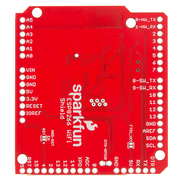
Hi, SparkFun WiFi Shield - ESP8266 has a Auto-Programing Mode circuit that is supposed to use DTR signal to auto configure GPIO0 to GND during uploading. How is it going to work if we must power down an up the ESP8266 ? Is there any special config to use this resource ? ThankYou Regards
Good eye! If you close the DTR jumper, the DTR signal can pull GPIO0 low when the ESP8266 needs to be programmed. That DTR signal also goes through a 0.1uF cap to the ESP8266's reset line - so when DTR goes low, it'll also briefly toggle reset to cycle the chip into bootloader mode.
This section of the tutorial explains re-programming the shield in a bit more detail. It describes using a wire from GPIO0 to GND to enter the bootloader, but the backside jumper should work as well.
Hi Jimb0, I did some tests and it's not possible upload codes to ESP8266 using only DTR to activate RESET and GPIO0 even with 0.1uF or 1uF CAP. The upload runs OK only int two situations: 1) when connecting GPIO0 direct to ground and using DTR to reset ESP8266. 2) When using DTR to set GPIO0 to ground and RTS signal from FTDI cable to reset de ESP8266.
I tie XPD_DCDC to RESET on all of my ESP8266EX-based designs, and I need a FET on the reset pin to be able to pull it down -- it sinks 30 or 40 mA of current, which most MCUs can't provide. I don't remember if the high current consumption is due to the RESET pin alone, or due to tying it to XPD_DCD, but it's worth checking with a multimeter to see that it's actually "trying" to pull the pin down.
Also, if I remember correctly, Windows has a nasty bug that prevents you from toggling one of the control lines (I think it's DTR) by itself -- i.e., you have to set the control line to the new state, then toggle the other control line to actually update that state. My memory is foggy, but it's either specific to USB CDC devices, or COM ports in general. May want to look into it.
No mention of what sort of antenna is required?
There's a built in 2.4GHz trace antenna that works well and a U.FL connector for larger gain external antennas. The adhesive one works well for me.
Can we have one of these with an FTDI built in for SDK programming? Would make life so easy!
Me too. I'm often reflashing with NodeMCU LUA. On the other hand, the level shifters built into this design should let you use an Arduino Uno or RedBoard as an FTDI, if you swap TXD and RXD, see my example sketch.