Frederic L
-
Disclaimer
07/12/2018 at 08:20 • 0 comments![]()
Ok so I thought I should warn you now, I DON’T KNOW WHAT I’M DOING.
Be ready for any outcome. Maybe I’ll end up having a working flip-dot display, maybe I will end up in jail for burning down my building doing activities outside of my insurance coverage.
Though I passed most smoke tests successfully over the past few years playing with Arduinos, I don’t have any formal training in electronics and I cannot guarantee that what you see here will fall in the best practices category.
I rely mostly on what’s available online from fellow hobbyist, and guess what, there isn’t much about flip-dot displays out there.
I’ll do my best to make it work and hope to get some useful feedback from more knowledgable/experienced people out there, and if anything, help somebody else with their flip-dot displays.
Alright, enough talking, let’s get into it.
-
A bit about pricing and sourcing
07/12/2018 at 09:58 • 3 commentsSo, one morning, I wake up, scroll through some Reddit posts (one of the bad habits I have), and stumble upon a guy posting about his flip dot display.
Well, it didn’t take me long to figure out I ‘needed’ one. Before that day, I had never heard of those displays, though probably I had seen some on busses or at airports, but never thought about it from a technical point of view.
I browsed internet and found that these things are pretty expensive. Especially when you include the shipping fees.
You pretty much have 3 possibilities discussed below:
- Buy a brand new display with a driver ($$ - $$$)
- Make your own display from scratch ($$$)
- Buy a used display with or without a driver ($ - $$, my case)
BRAND NEW DISPLAYSThe brand new route is probably the easiest (and least fun) route, but it will guarantee you get a working display with a proper controller quickly. Though, it comes at a price :
AlfaZeta makes brand new displays, with a controller board. Their XY5 displays (14x28) sells around 500€ (VAT and shipping included). That’s 1.27€ per pixel, but you get the comfort of having a working, brand new, customisable display with a driver/controller board included.
Another high end brand, Breakfast LLC provides plug and play displays for professionals, but their website suggests those would be at a price waaay beyond what I'm willing to put, so I didn't bother asking for a quote :
Breakfast LLC Flip Discs
MAKE IT FROM SCRATCH If you want to make your own board from scratch, ie. buying flip dots new from a supplier, then make your own PCBs for the display and controller, be ready to break the bank. Each dot is a relatively complex component with coils and moving parts.
These are a few suppliers I could find :
I'm waiting for the quotes of the last two, but Magsign made me a quote for 1000 dots for 3500$, so 3.5$ per pixel, and this doesn't include the manufacturing of the PCBs, controllers, and other required components to make it work. Their dots seem to be of very high quality though, and are rated for more than 100 million flips !!!
Even if I would have liked the flexibility and challenge of making it all from scratch, the price (and the perspective of making a schematic and soldering of 1000 dots + 1000 dual diodes) put me away from this solution.
GET A USED DISPLAY Most used displays come from urban busses. Either the bus got scrapped and spare parts end up on the market, or they are being retro-fitted with the more modern LED displays.
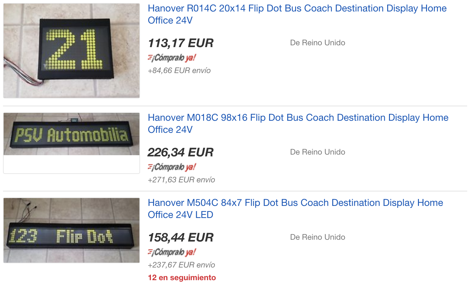
Some specific reseller offer those displays, such as Rollsign Gallery, or PSV Automobilia.
Common brands include Hanover, Luminator, and ANNAX and eBay is the easiest place to find flip dots displays, though watch out for the delivery and import fees as it may double the advertised price.
At the time of writing, a used Hanover display sizing 98x16 can be found on eBay for 220€ + 270€ for shipping (seller psvautomobilia). That’s 0.31€ per pixel, but that’s a bit too big for my use.
![]()
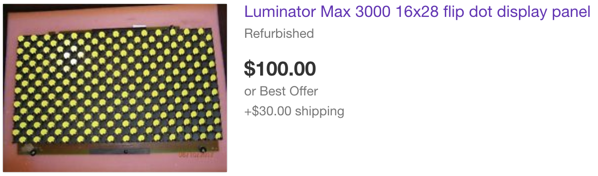
A Luminator (16x28) sells for 100$ + 30$ shipping (USA Only). That's 0.25€ per pixel (at today's USD-EUR rate). (Seller frankie615us11).
![]()
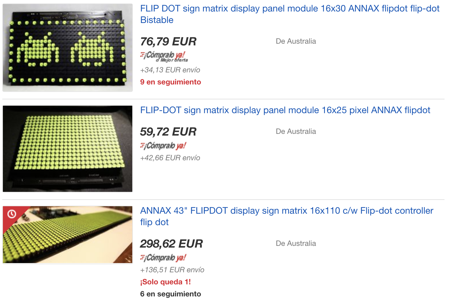
A bit further down on eBay I found some ANNAX displays, 30x16 pixels, for a total of 110€ shipping included (seller discountbuys_2012, open to offers). That’s 0.23€ per pixel, best I could find so far, so I took one, and half a day later I decided to take a second one. That’s twice more fun right ?
![]()
I should end up with a 16x60 dots display, which will be big enough to display a wide range of stuff (not sure what I'm going to do with it yet, I'm open to suggestions).
The pixels are pretty square and with very little clearance, which makes it cleaner, and the integrated LEDs on each dot would make it possible to read the display at night, although it will require more coding and wiring.
NOW THE FUN PART. Those come without any controller board or driver (available separately on eBay at... 160€!). Which is what this project is about: Designing the control module, by reverse-engineering the flip dot display, and use a micro-controller (ESP32), to drive the whole thing.
-
Single dot anatomy
07/13/2018 at 07:45 • 0 commentsI will quickly cover how a dot flips before looking at the bigger picture.
![]()
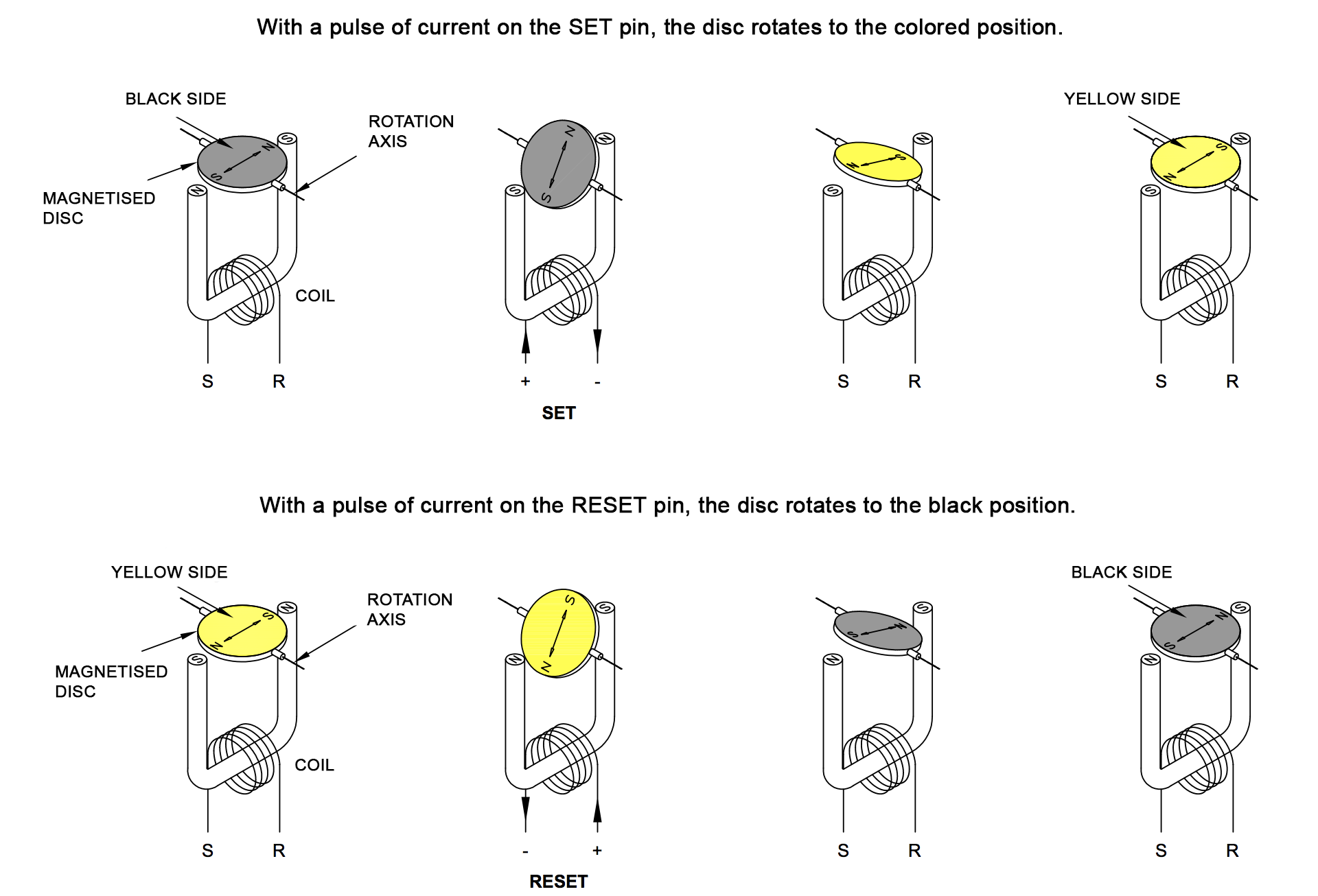
Each dot contains a permanently magnetised moving surface (usually a disc, or a triangle in my case), usually black on one side, and yellow on the other.
To turn the disc, ie. flip the dot, a coil is placed underneath, along a rod (core) of ferromagnetic metal. When a short pulse of current goes through the coil, the metal core becomes magnetised, with a polarity depending on the direction of the flow of current through the coil during the pulse. Once the pulse is over, the core will retain it's polarity until a new reversed pulse is applied.
When magnetised in either direction, the metal core will attract or repulse the permanent magnet on the yellow and black surface, hence flipping the dot and locking it in it’s new position.
![]()
(Pay attention to the polarity of the core tips, drawings from Eldi datasheet)
Why does the core retains it's polarity once the current is removed you may ask (as opposed to electromagnets) ?
Well, I'm not an expert but I believe the core is made of a metal with specific magnetic properties, such as high permeability (its ability to become magnetised when subjected to the magnetic field of the coil), and high remanence (its ability to remain magnetised afterwards).
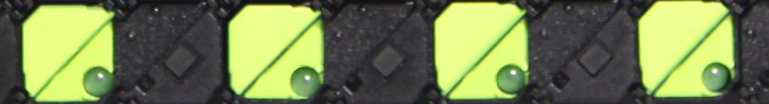
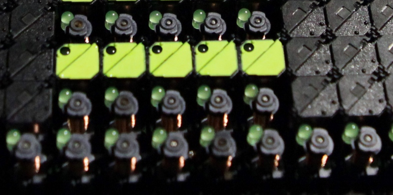
This would turn the ferromagnetic core into a permanent magnet once magnetised by the coil, and it would remain so until the next opposite pulse through the coil.On the picture below you can clearly see:
- The permanent magnets (small squares on the upper-left black triangles)
- The vertical copper coils underneath each dot
- The tip of the ferromagnetic core that sticks out from the center of each coil.
- An associated LED for each dot on this specific display
![]()
ANNAX flip dot anatomy (source)
One advantage of these displays is that you can remove all current and the display will remain as is, hence very cost effective for static messages.
We'll discuss later the power requirements to flip 1 or more dots simultaneously but for now, let’s take a step back and look at how a whole display is made.
-
Matrix layout and controller's job
07/14/2018 at 07:57 • 1 commentFlipping a dot isn’t too hard, but how do you proceed when you have to control hundreds of them ?
![]()
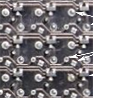
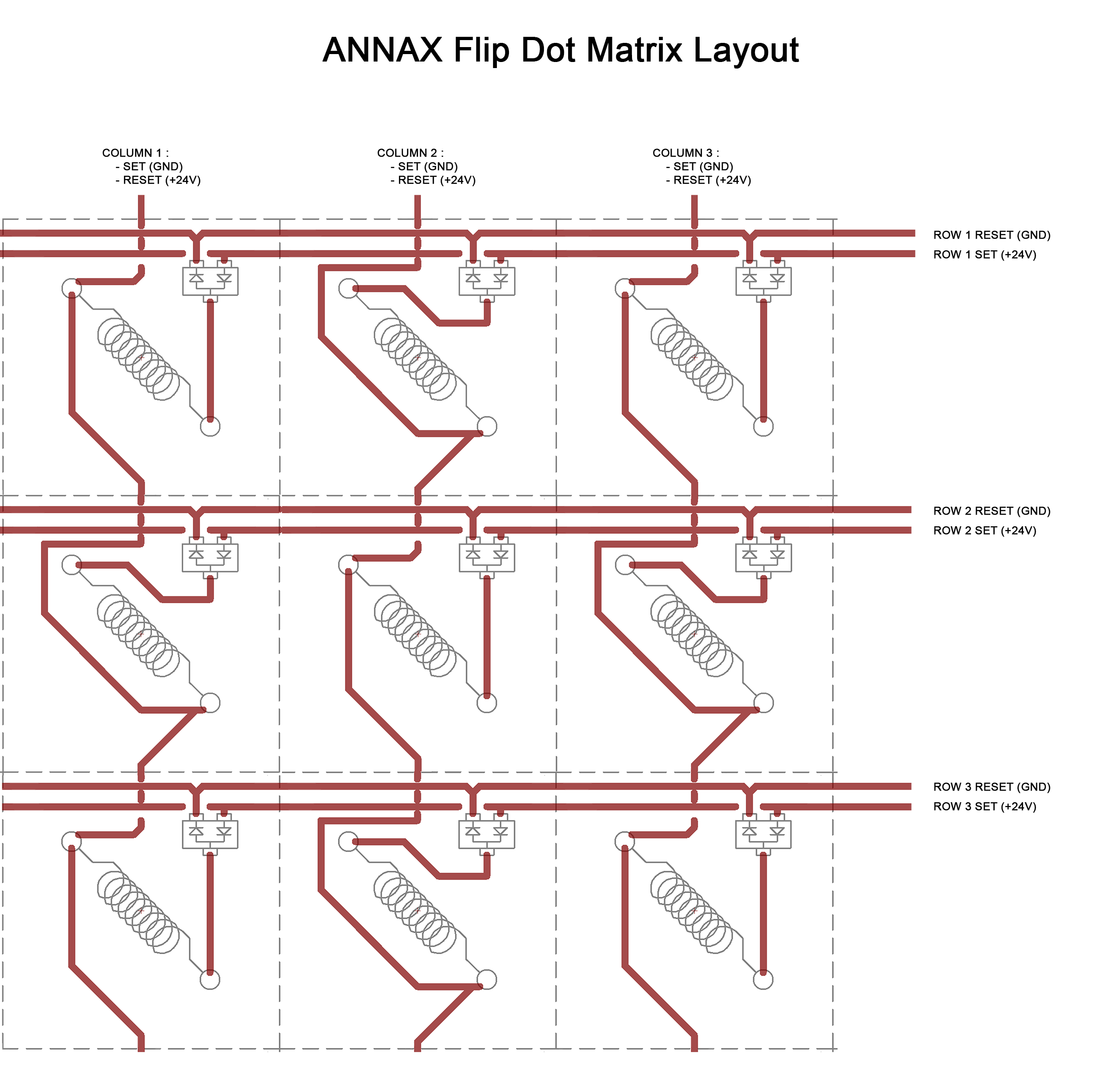
If you look at the picture below (sorry for the poor quality, I can’t take pictures of it myself as I haven’t received the displays yet), you can see the display's back board. I extracted a 3x3 dots area.
![]()
You may be able to distinguish the connections. Below is a drawing of it to make it clearer (I omitted the part associated with the LEDs). Also the columns connections are not visible on the picture as it seems they are on the other side of the PCB.
![]()
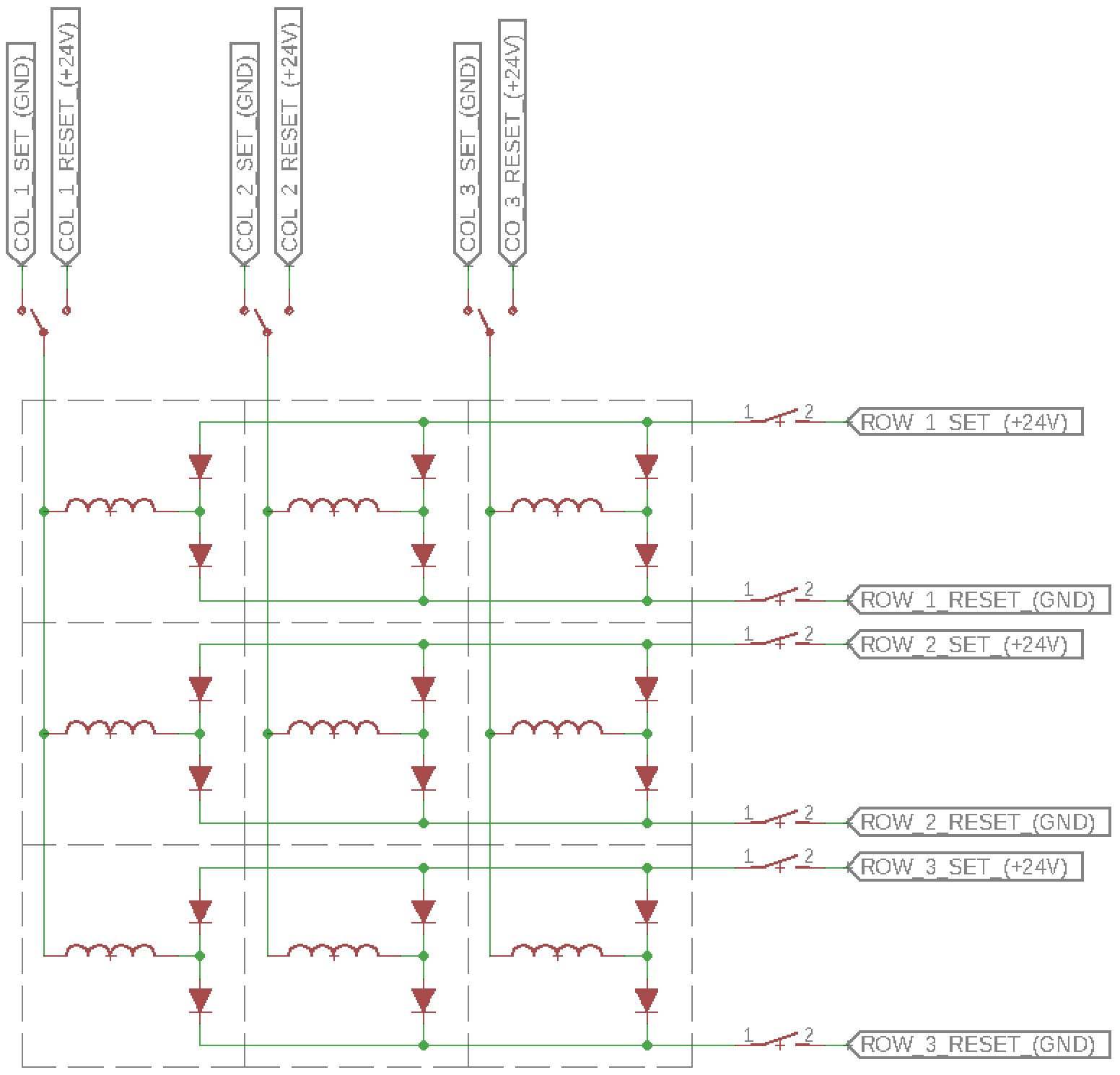
Drawing of 3x3 dots above Below is an equivalent schematic, but clearer and easier to work with :
![]()
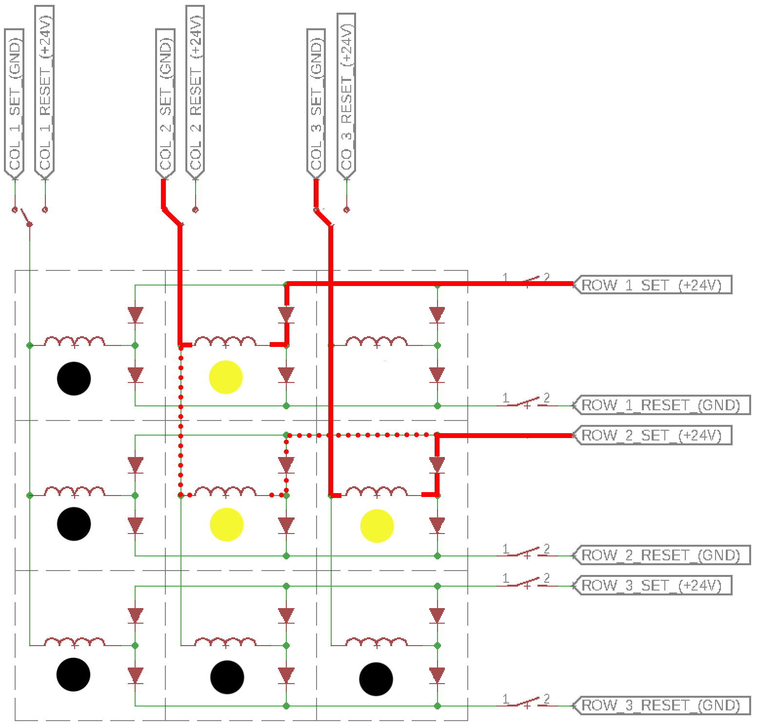
Simpler equivalent schematic of 3x3 dots
From now on we’ll stick with this schematic and look at the theory of flipping dots in such an assembly.
Each column can either be connected to GND or to +24V (respectively SET and RESET the dot).
Each row has two separate inputs, +24V to SET the dot, and GND to RESET the dot.
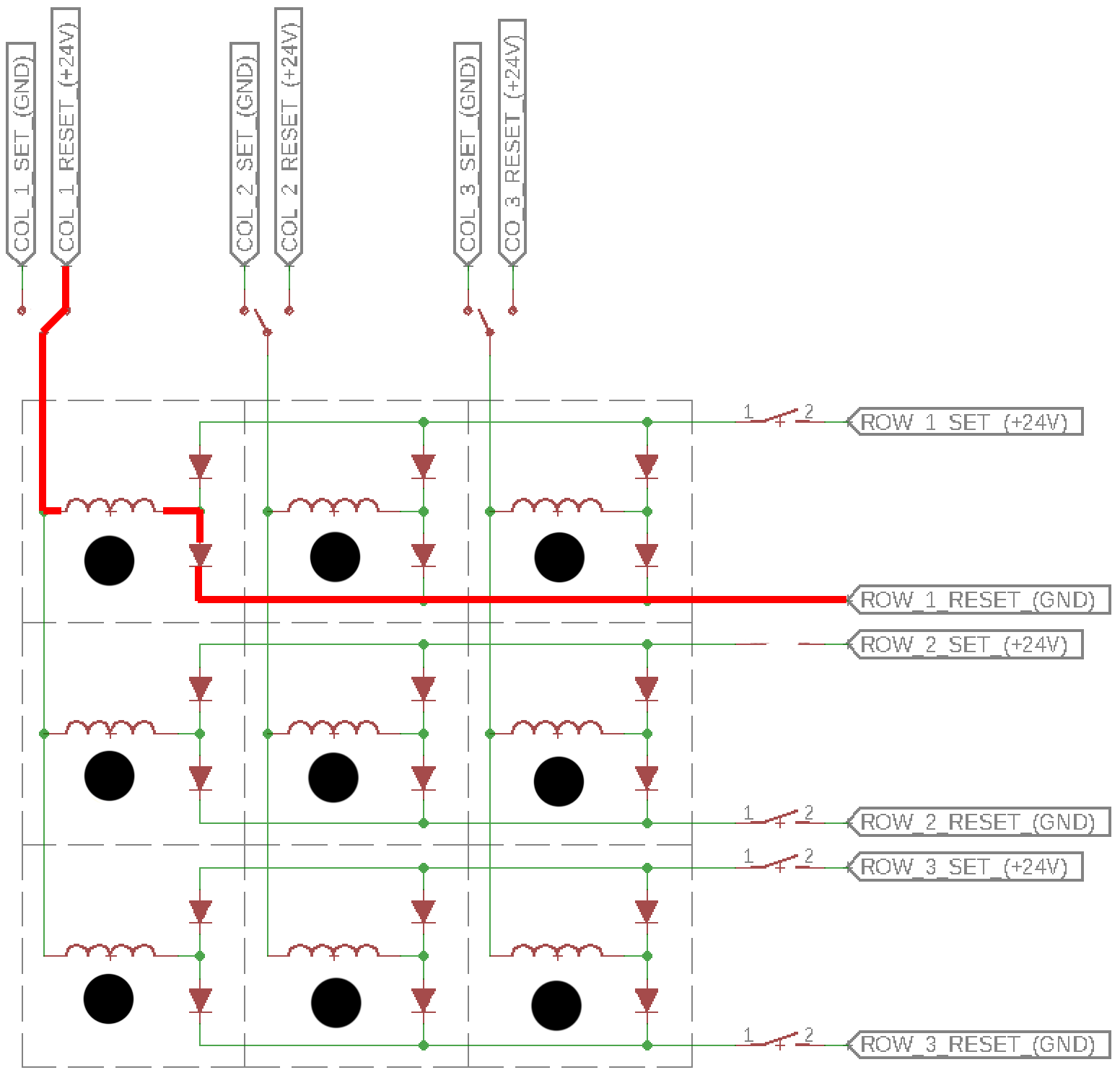
Let’s consider a blank (black) display and we want to flip the upper left dot (column 1, row 1). We should connect ROW_1_SET to 24V, COL_1_SET to GND, send a pulse of 24V, and open the switches again. Current can only flow through the first dot, as it is blocked by the dual diodes (those are required otherwise the current will be free to flow through every other coils) and open switches elsewhere.
![]()
To UNSET it, we have to reverse the direction of the pulse through the coil. So we connect the column to +24V and the row to GND.
![]()
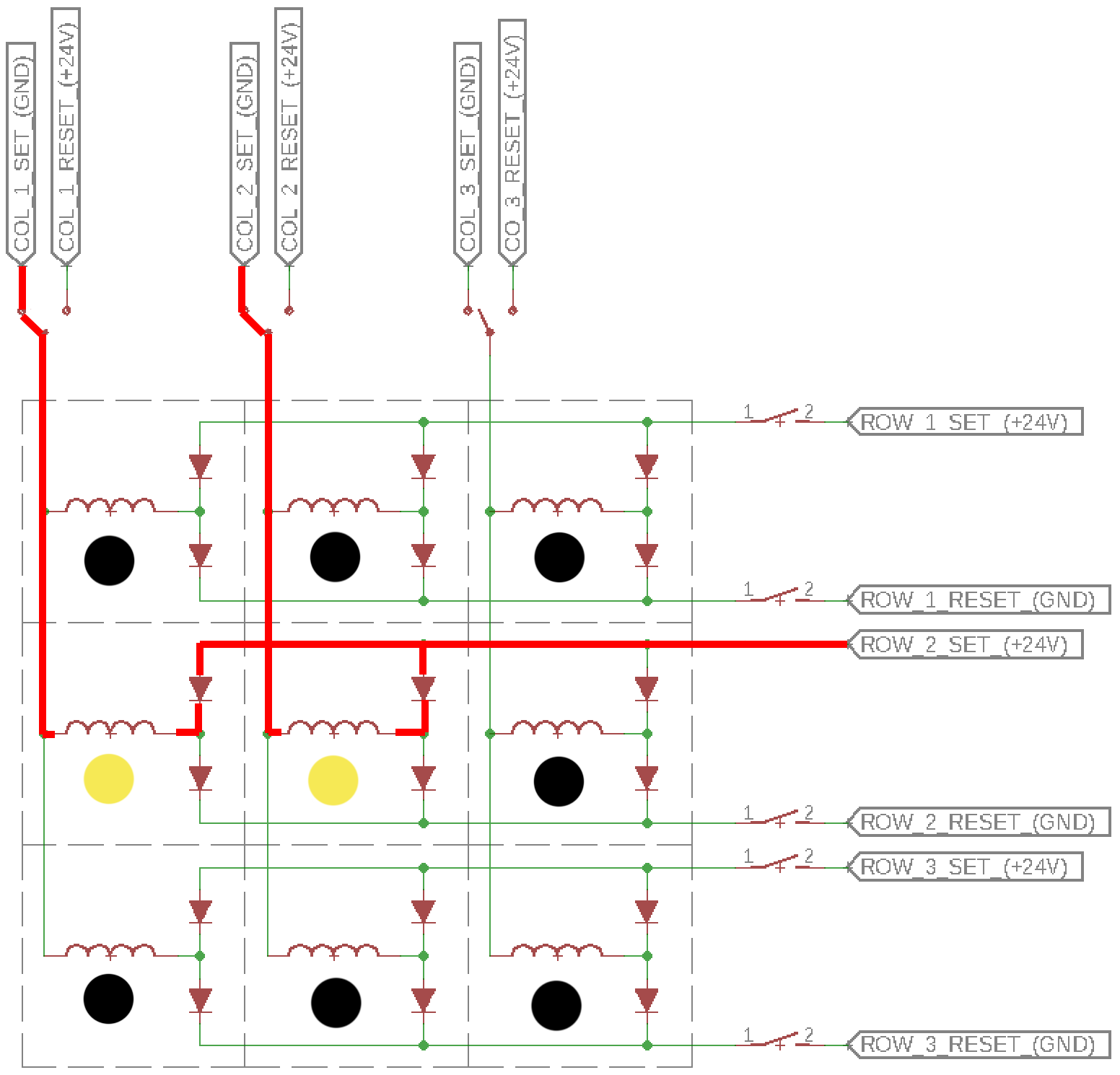
To flip several dots at the same time, for example (column 1, row 2) and (column 2, row 2), we can connect COL_1_SET and COL_2_SET to GND simultaneously, and send a pulse through ROW_2_SET.
![]()
Note that NOT ALL combination of 2 or more dots can be set at the same time. We cannot simultaneously set dots that don't share the same column or same row without affecting other dots on the board. Below an example of trying to set (col 2, row 1) and (col 3, row 2).
![]()
You can see that the middle dot (col 2, row 2) will have current flowing through it and will be SET even if we were not targeting it in the first place.
It's obvious that a mishandling of the switches may easily create shorts and turn the flip-dot in a smoke generator, eg. by closing ROW_X_SET and ROW_X_RESET at the same time.
We established how to flip each dot of the display by a careful combination of connections on each row and column. Moving those switches will be the job of the controller which will be commanded by the code (driver) on the ESP32.
![]()
-
Unboxing the ANNAX Flipdot display
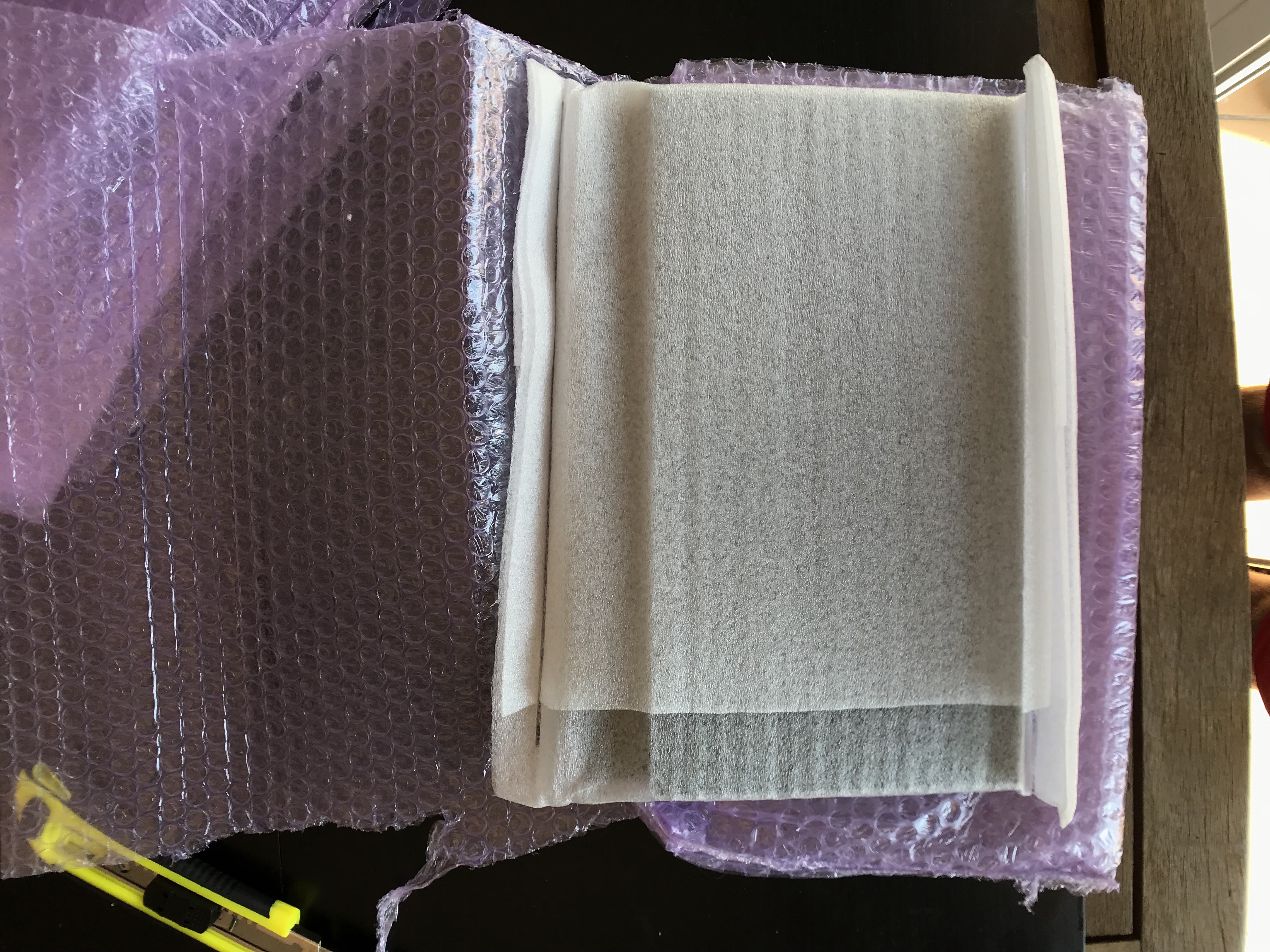
07/26/2018 at 17:20 • 0 commentsFinally, after a few weeks of waiting, I received this morning my two ANNAX ZM16C30 flip-dot displays. I'm extremely pleased with the packaging. Several layers of styrofoam, bubble-wrap, and foam sheets kept the precious boards and flippy dots secure during this journey across the globe from Australia to Spain.
![]()
Came with a personal note on a postcard :
![]()
And a small bag of several replacement dots. Some don't seem to be usable directly as some are missing their magnet. But nonetheless very appreciated and could be very useful to make some repairs at later stage.
![]()
Double wrap in bubbles and foam :
![]()
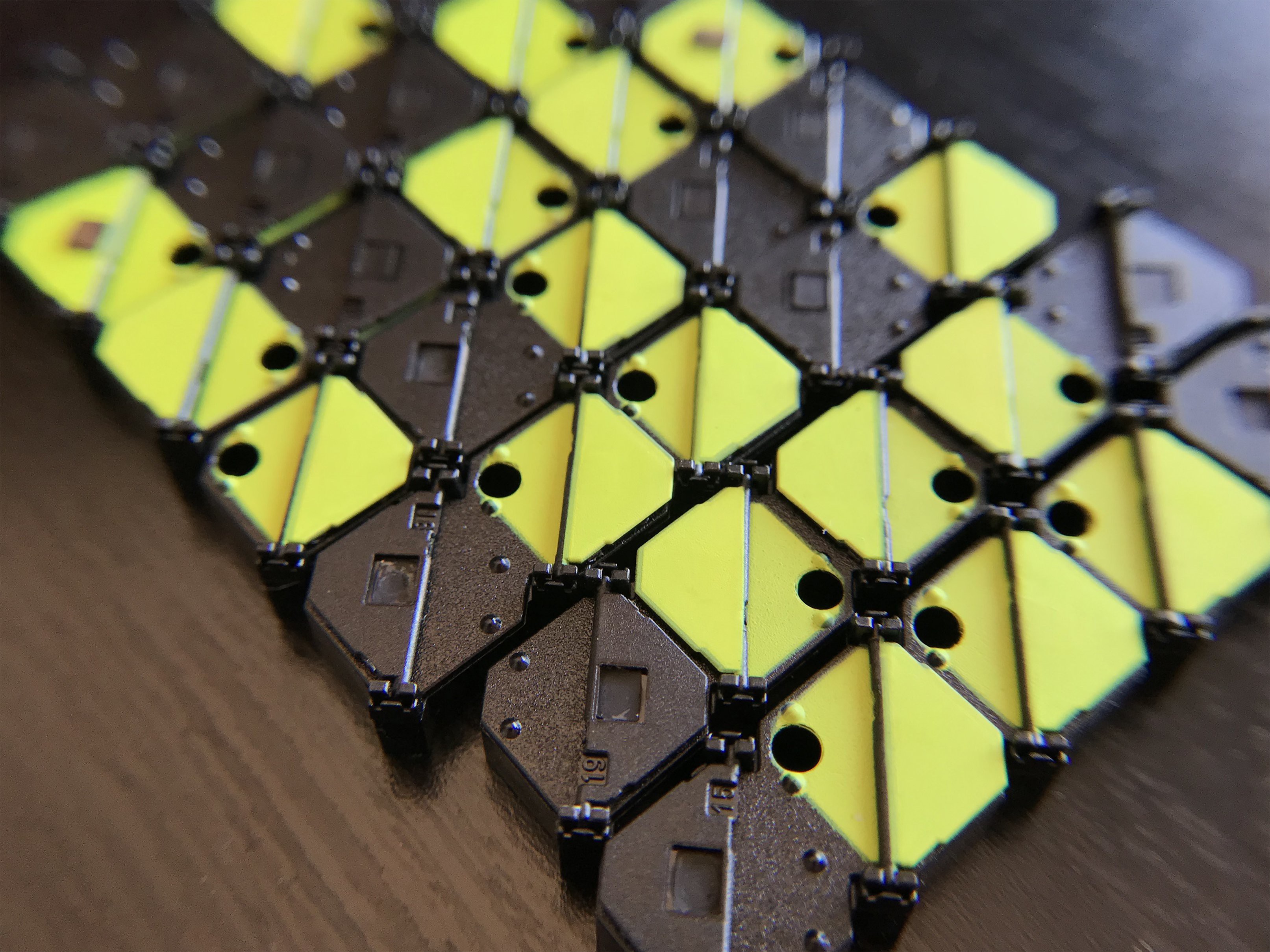
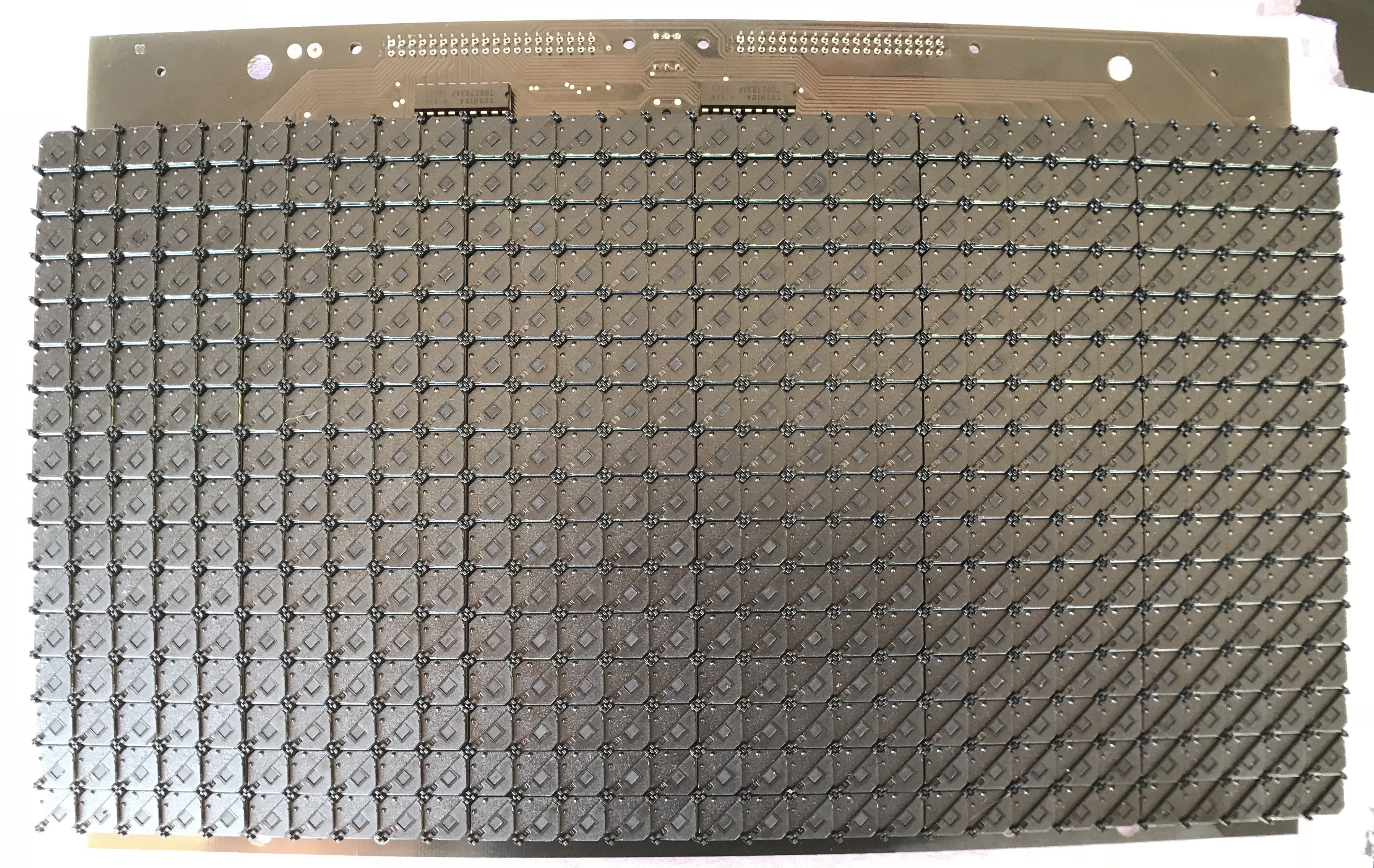
High quality manufactured board and clean dot matrix. Pretty happy with the product so far.
![]()
![]()
Some close up shots.
![]()
![]()
Now will start the reverse engineering. The board comes with two 40pins connectors, and a few other chips on it as seen above. I'll try next to find out what they are for, and which pin of the connectors go to which columns and rows. Stay tuned !
-
In depth ANNAX layout and design
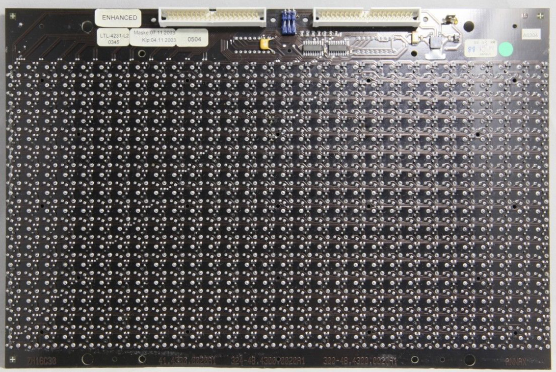
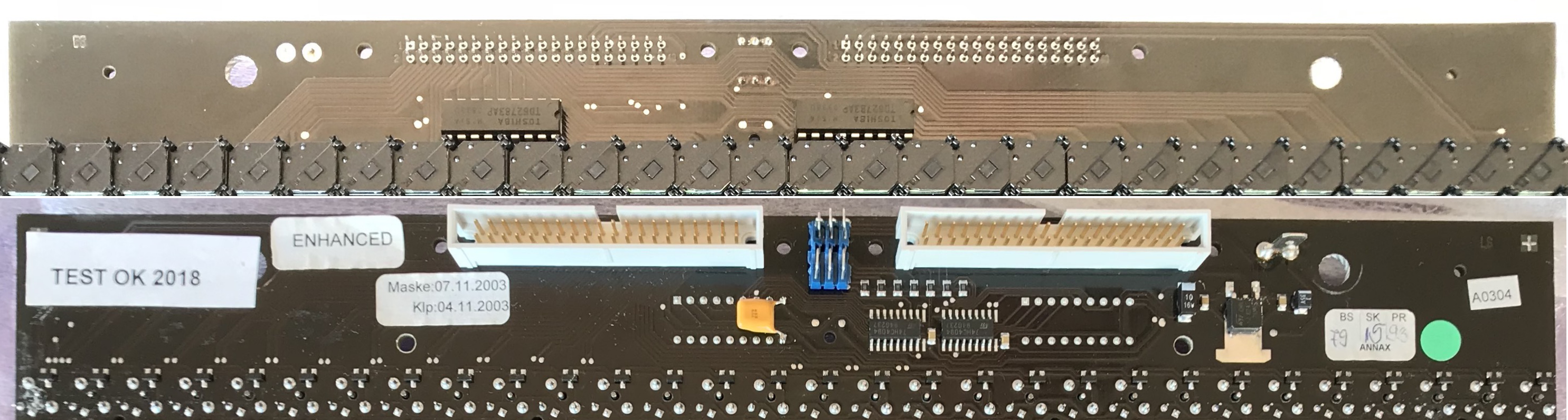
07/29/2018 at 08:20 • 1 commentI had a few hours to spare yesterday, so I pulled out my multimeter and started figuring out the board layout (reverse engineering to sound fancy). I won't go over the matrix layout as it has been covered in a previous log, but I will describe the top part of the front and back board and my findings regarding the pins of the two connectors. Here is a global view of the front and back top part.
![]()
There isn't much to it, and you'll see that the few ICs on there are for driving the LEDs only. The flip dots on the other hand, are connected to the pins of the two connectors at the very top.
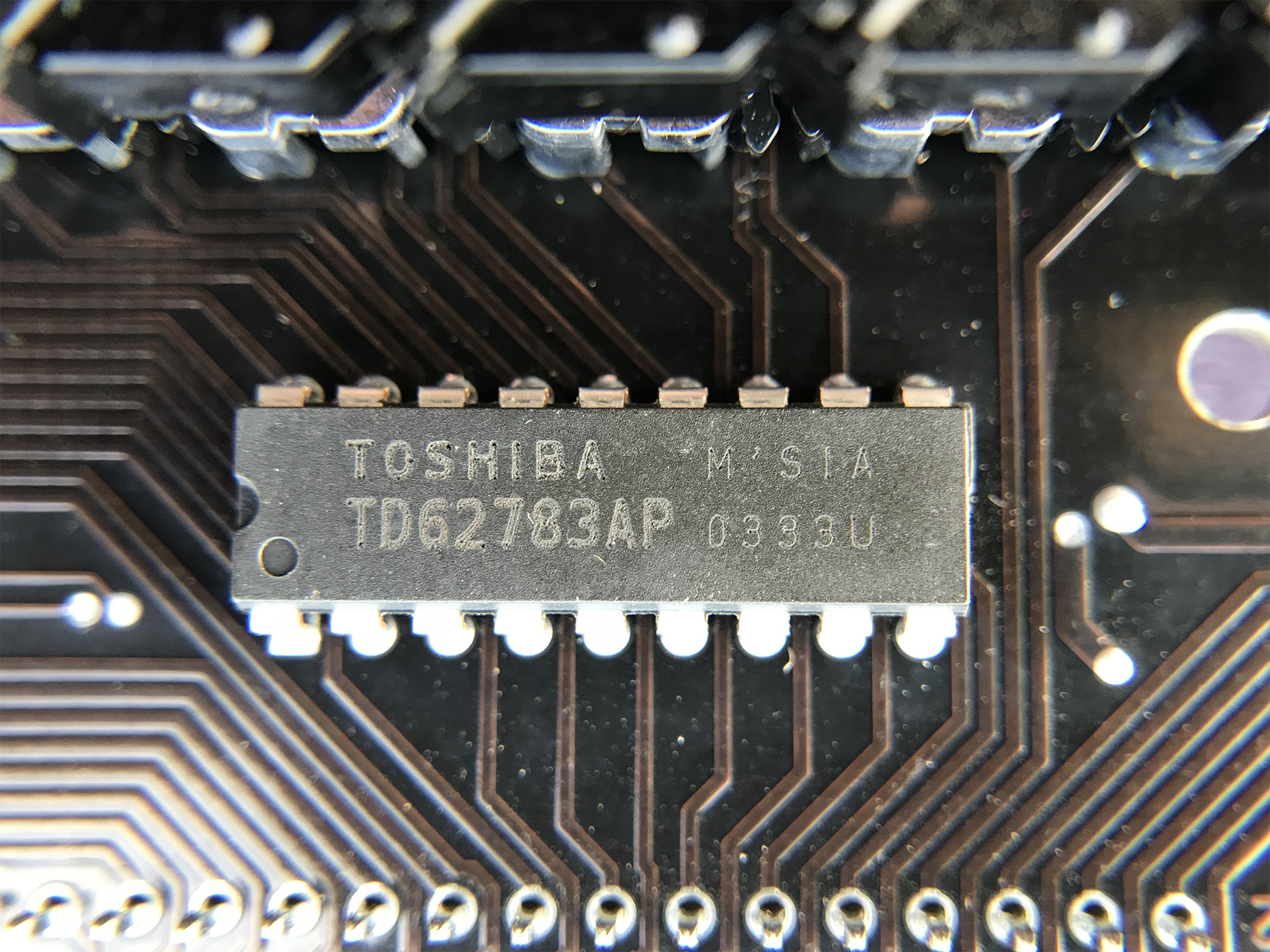
The front part is pretty empty, and not much to say besides the two TOSHIBA TD62783AP 8 Channels Source Driver.These will source current for the LEDs for all 16 (2x8) rows.
![]()
We can also notice the trace routing going from the left connector (when looking at the front of the display) to each column. This is indeed the columns lines that will either source or sink current according to whether we set or reset the pixels.
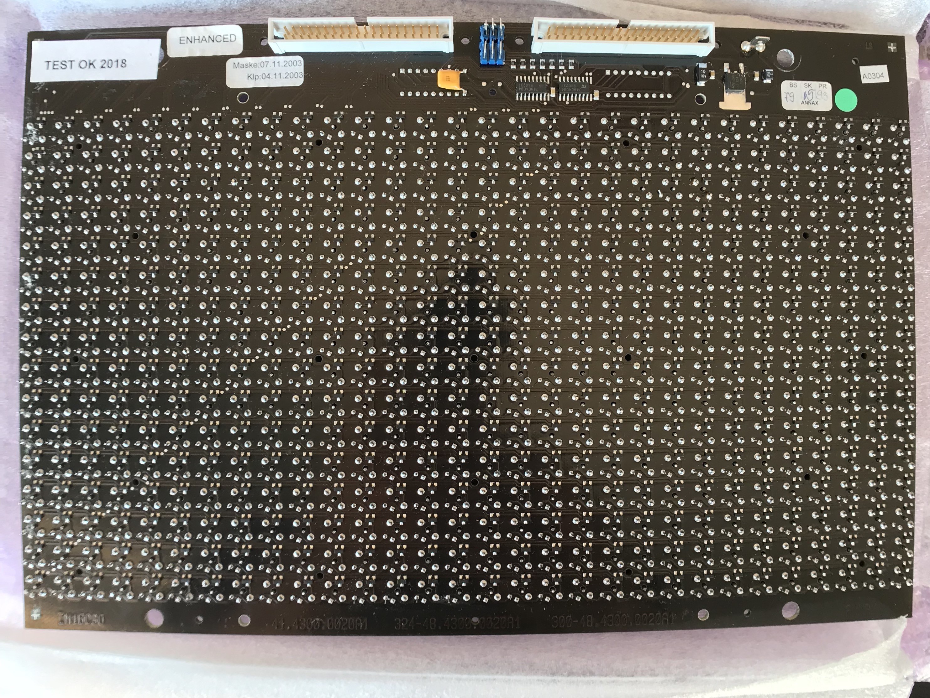
The back part is more interesting. From right to left :
![]()
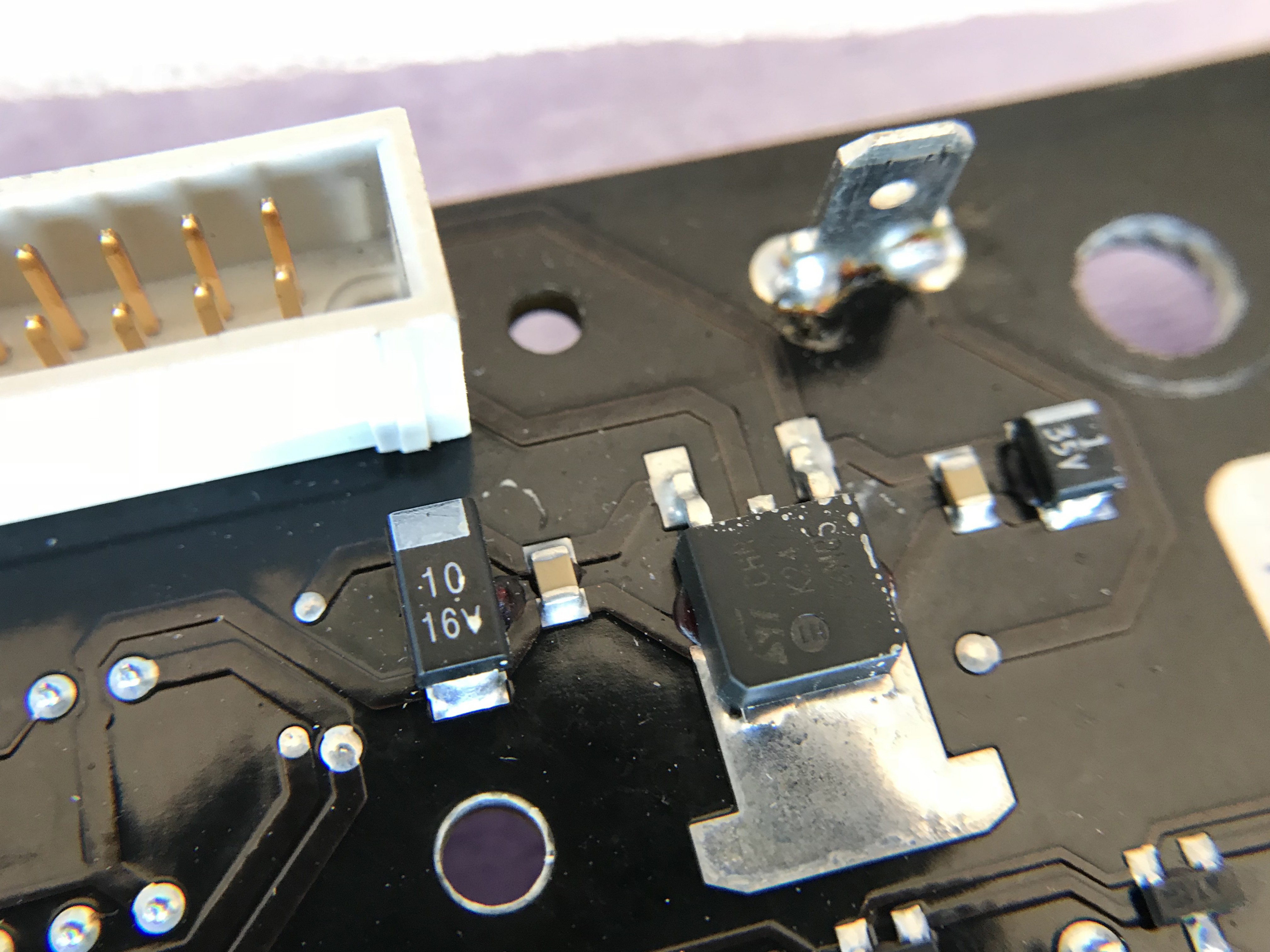
On the top right you see a tab connector. This one is for the LEDs power source, as its line goes directly to the two TD62783AP pin 9 (VCC) mentioned above.
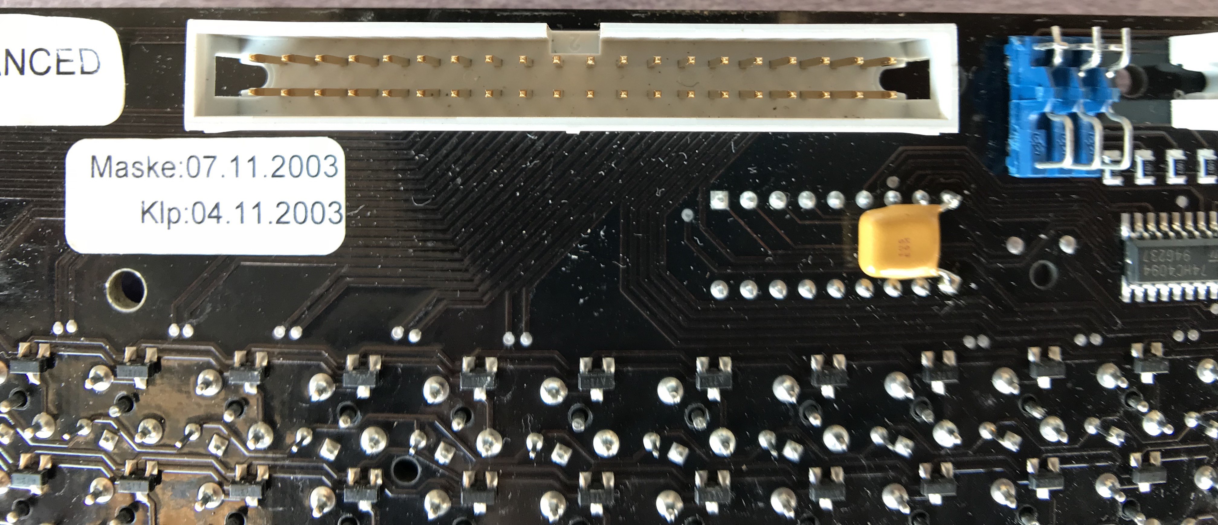
Below it is an L78M05 voltage regulator. It takes power from the 40pin connector, regulates it to 5V and powers the other ICs on the board. The few caps around are quite common on power supplies, mainly for decoupling.
![]()
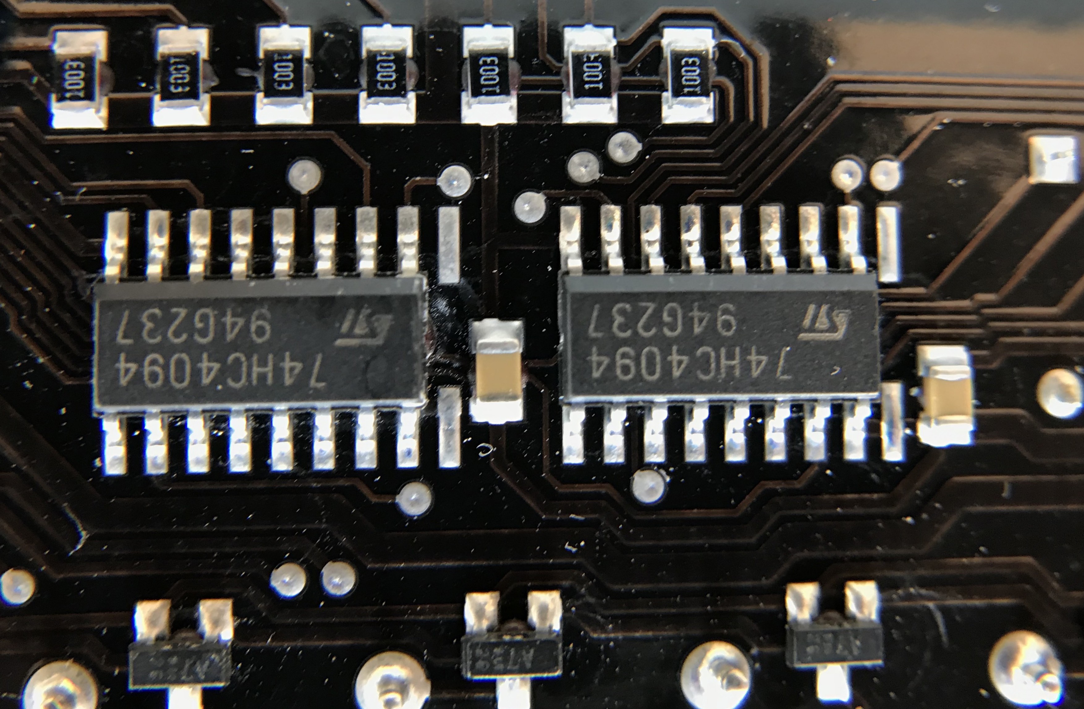
Next come the two 74HC4094 shift registers. Those are controlled from some pins on the 40 pins connectors, and their outputs go directly to the Toshiba source driver on the front. Together they control the LEDs power on each of the 16 rows.
![]()
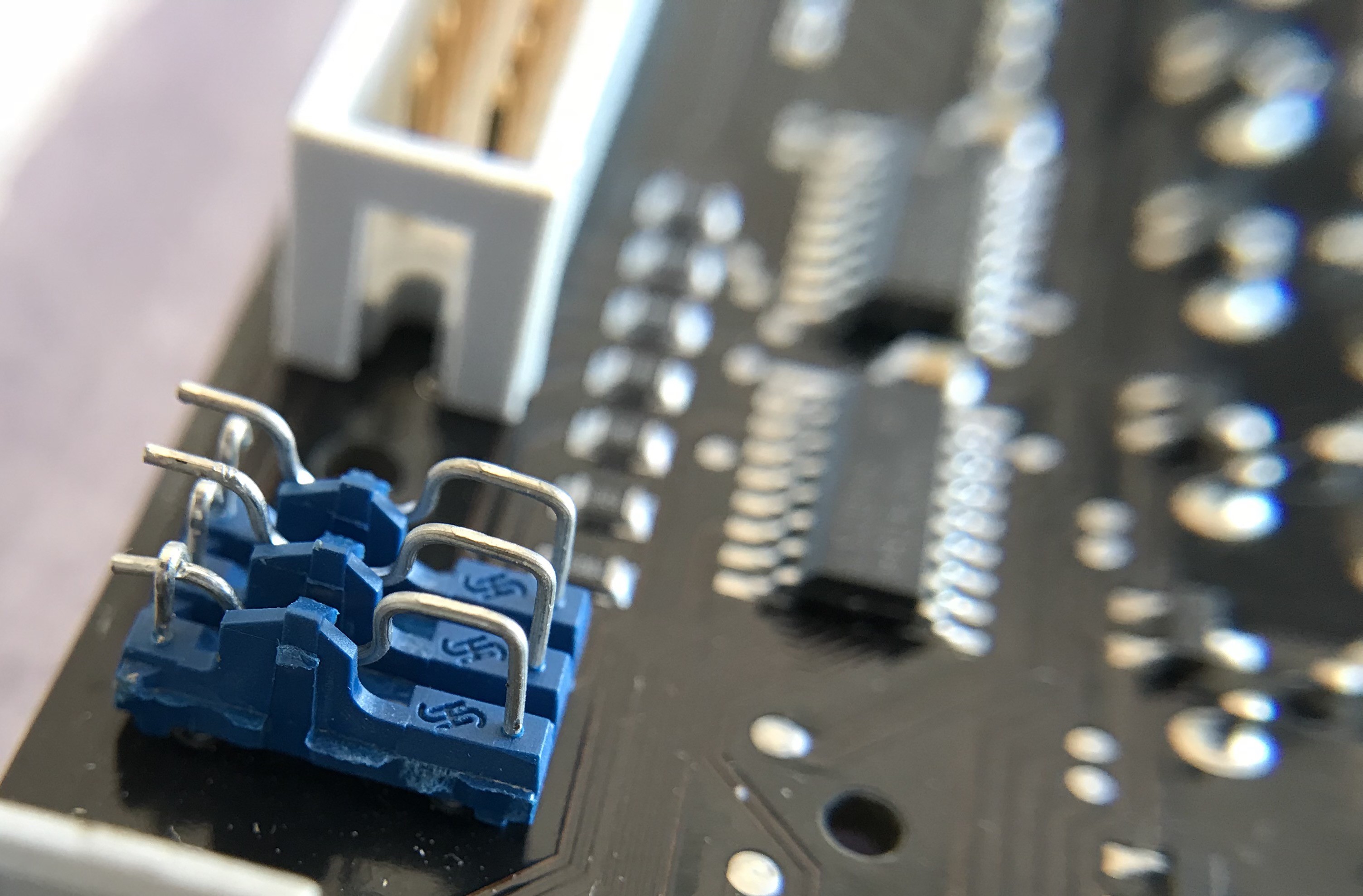
The blue thing here are three switches. On the photo you can see switch 1 is closed (the left lug goes below the hook, making contact), whereas the other two are open. Each switch connects one different pin of the 40 pin connector to the DATA (D line, PIN 2) of the first shift register (the second shift register gets it's data from the output of the first shift register. My belief here is that those switches allow to selectively control several displays LEDs with different data lines.
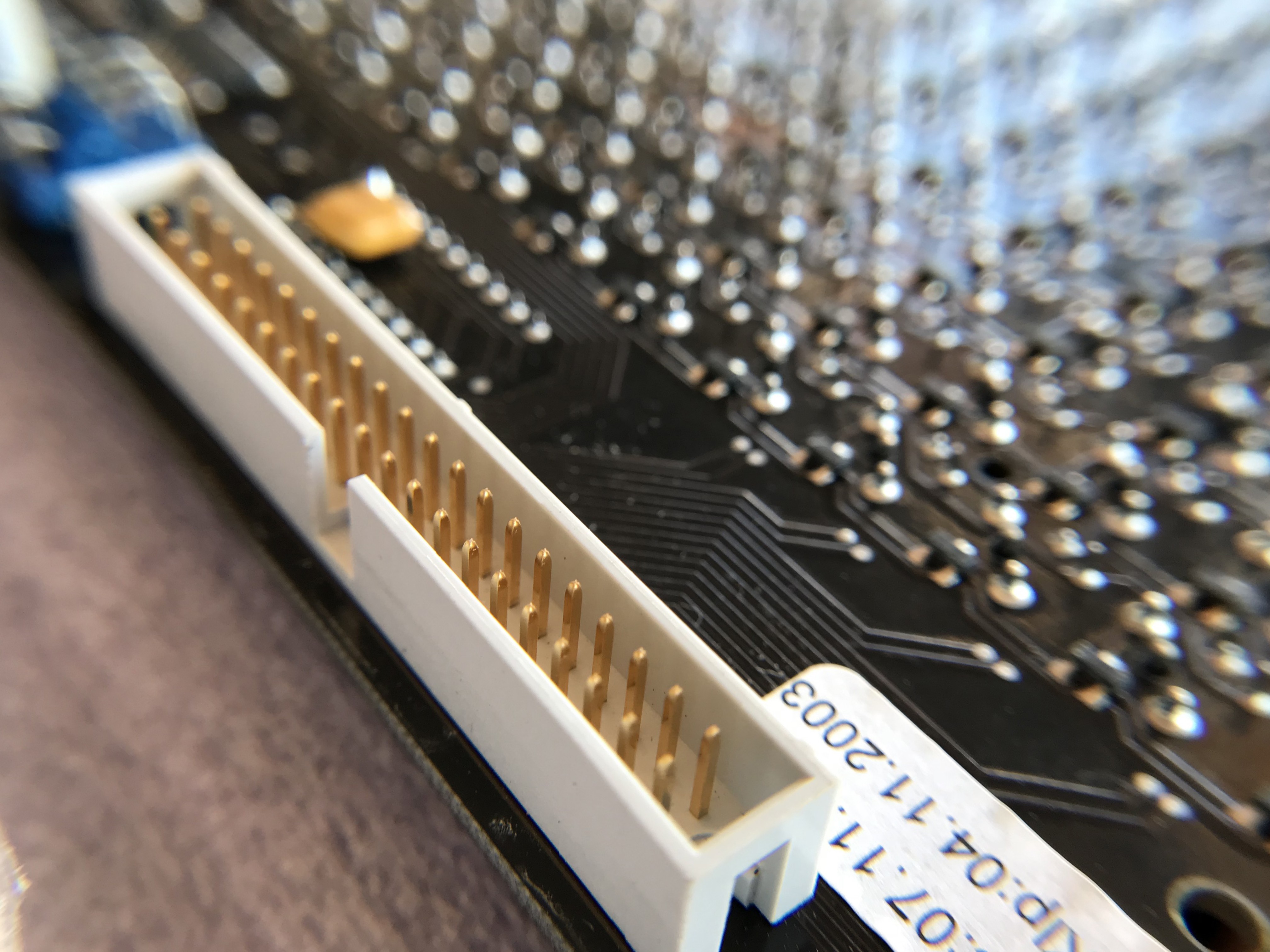
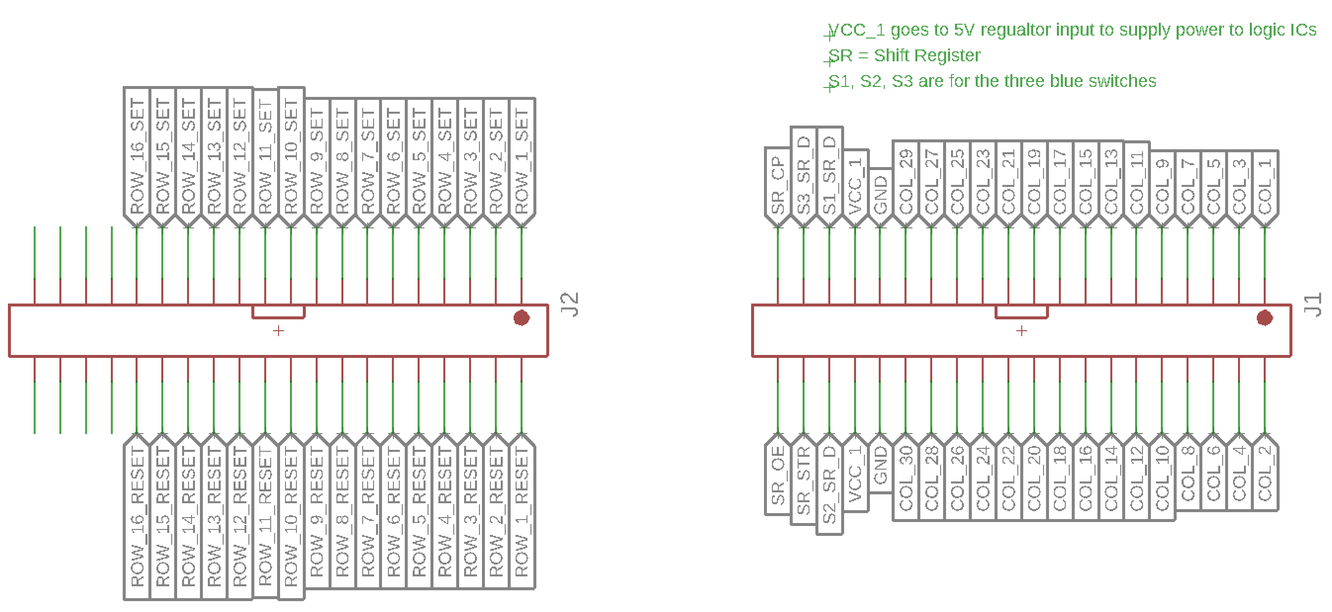
Finally, the most important and interesting part for the controller, are the two 0.1" pitch IDC 40-pins connectors.![]()
And here are what each pin is for :
![]()
This view is as seen from the back of the board, ie. pins going towards us.
From there, let's make a controller.
-
Controller prototype schematic !
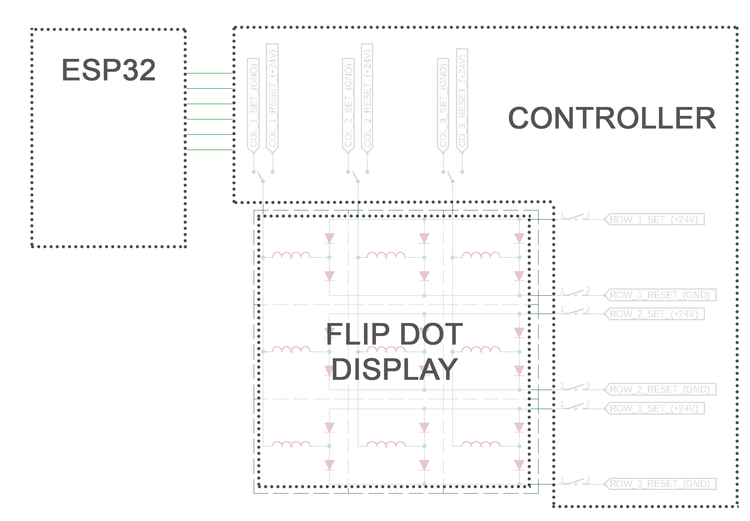
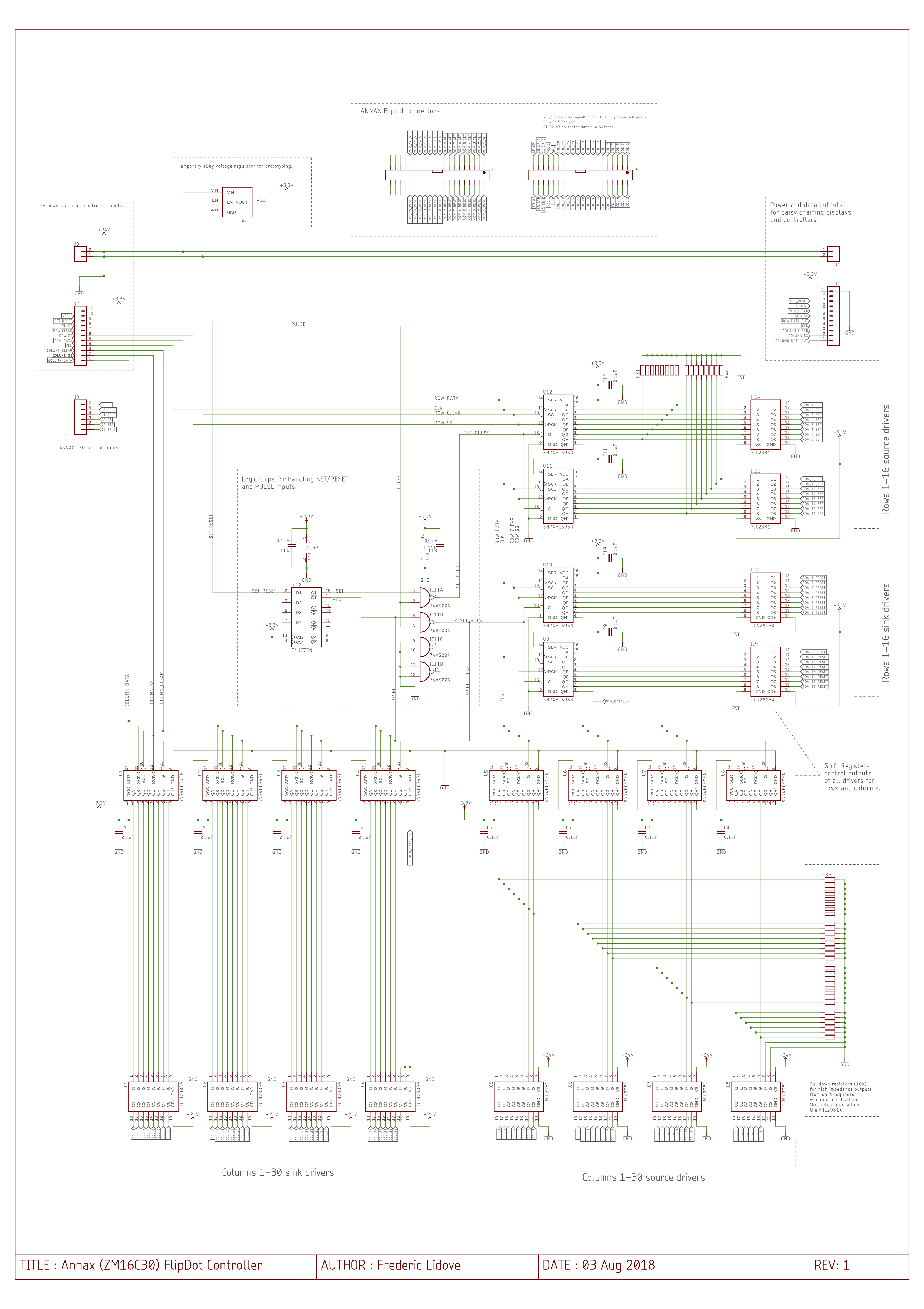
08/03/2018 at 09:49 • 0 commentsFinally ! Here comes my strategy to control the flipdot display. This is the control board prototype, and drives ONE display. Each display will have it's own control board and can be daisy chained (ie, only one micro controller needed and it will control all the displays stacked together.
It's still a prototype as I'm not sure it will work (it would be too good if it worked at first try). Also I still have to design the power supply for the board logic chips. For now I'm using a cheap eBay switching voltage regulator to provide 3.3V or 5V to the ICs from the 24V supply, but this will be integrated in the design in the final version. The ESP32 being 3.3V and the chips on the display being 5V, I'll have to do some level shifting in the final design (I keep this for later once I'm sure it works).
I tried to annotate as much as I could to help follow the logic of the board, but next log will go more in depth into the chosen ICs and describe the overall functioning.
Available in PDF version for higher quality.
![]()
-
Schematic, ICs, and logic description
08/03/2018 at 10:24 • 0 commentsAs seen previously each dot is connected to three lines :
- Column SET / RESET is either sourcing current from +24V or sinking current to GND
- Row SET is sourcing current from +24V
- Row RESET is sinking current to GND
So we need to be able to Source Current from the +24V power supply, as well Sink Current to ground, both on the same line in the case of the column trace.
- Source Current with MIC2981 driver
This chip is a 8-channel source driver, it is connected to the power source, it has 8 logic inputs that control 8 high voltage outputs. When an input is HIGH, its corresponding output is sourcing power.
- Sink Current with ULN2803 driver
This is pretty much the same as the MIC2981, except when an input is high, it connects the output to ground and sinks current through it.
- Controlling the drivers with shift registers (SN74HC595)
Several solutions available here, one could use a multiplexer with a binary counter to switch from one row to the next, and from one column to the next, but for more flexibility I chose to control the drivers with shift registers. These will give me a complete control over which columns and row I’m selecting, and in any order, through fast SPI communication. If required I could also flip several dots at the same time, but power will be limited to 500mA for sourcing and sinking from the drivers.
- Quad latch for SET or RESET selection (CD74HC75)
One thing I want to avoid is to shortcut +24V to GND, which could be easily done with a simple mistake in the code such as having both the SET output and RESET output of the micro controller HIGH or LOW at the same time. To avoid this, and reduce the outputs required from the micro controller, I chose to use only one output which would be either HIGH for SET and LOW for RESET. This quad latch splits an input in two opposite signals which will restrict the system to be only in SET mode or only in RESET mode.
- NAND gate for enabling shift registers through pulse control (SN74AS00)
With this setup, the only way to control the pulse of current that goes through the dots is by shortly enabling the output of the shift registers. As we need to select which shift registers we want to switch on (either the ones for SET, or the ones for RESET), we can combine the SET AND PULSE or RESET AND PULSE. OE being active low, a NAND gate instead of AND is appropriate.
- Power sources
For the power supply, I will start with a MeanWell LRS 150-24, an open frame PSU probably overkill with 150W of power. I’ll select a final PSU when I’ll have figured how much power I need to run the display.
For the low voltage power, I found a small cheap adjustable switching PSU circuit on eBay, which offers variable output including 3.3V for the ESP or 5V. All ICs mentioned above are compatible with 3.3V or 5V inputs.
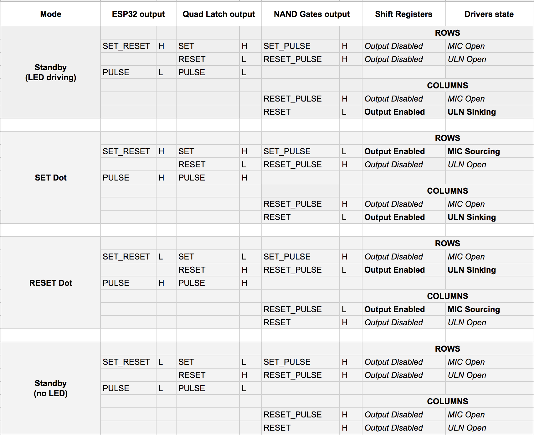
- Logic subtlety and controller available modes
If you look closely at the schematic, you'll notice that the columns sink drivers associated shift registers (bottom left) are not enabled through the SET_PULSE line as we could expect, but instead directly from the RESET line, bypassing the NAND gate. This is due to the design of the LEDs on the ANNAX display.
The LEDs have their anode connected to the shift registers on the display itself (controlled independently), and their cathodes are connected to the columns SINK lines. Therefore, when I'm not flipping dots (PULSE line LOW), I still need to enable the columns sink lines to control the LEDs, independently of the PULSE input.
Here is a table with the 4 different modes the controller can be according to the state of the SET_RESET and PULSE output lines of the micro controller :
![]()
-
Prototype PCB design
08/08/2018 at 16:04 • 0 commentsIt turns out the schematic from previous log contains around 200 wires, that is, for one display. I have neither the patience to cut to length and strip 400 wires nor do I have enough breadboards to accommodate for all the ICs in order to run my two displays.
So, for the price of extra breadboards and wires, I can have a PCB manufactured, which not only will eliminate (or at least reduce) the risks of mis-wiring, but also will keep the “lab” (read: my living room) tidy. The only downside is that I loose the flexibility of changing the circuit on the go, but I worked hard on the schematic (even harder on the PCB layout) and I believe it should work.
The PCB size is based on the available ANNAX mounting holes and should fit nicely on its back with a few spacers. I chose only through holes components for ease of soldering as well as for ease of changing burnt ICs (plan for the worse, hope for the best). The ones most susceptible to get grilled are the source and sink drivers, so I’ll mount those on sockets.
Having through-hole components all over the board, and trying to keep them all on the same side (reducing overall thickness) was a real challenge as it restricts the available space for routing, but I managed to make it work, hopefully without breaking too many laws of good PCB design (eg. the GND plane on the back has more signal lines cutting through it than I would have liked).
The PCBs have been ordered from JLCPCB. I have used a few time past and I was pleased with the results. Five boards for 16€, one week delivery for 24€, for a total cost of 40€ (standard delivery was 12€ only but I'm in a rush to get started).
Here are some screenshots of the layout, I took the liberty to make some silkscreen “art” on the back but the result might not be as expected as there are vias and through-hole pads literally everywhere.
![]()
Layout output from Eagle ![]()
Improvised "PCB art" on the back On the final board, at a later stage, I’ll probably use SMD components to have more space to integrate an appropriate voltage regulator, some level shifting chips, and the ESP32. Maybe a nice soldermask color, and higher quality surface finish, would make for a cleaner, all in one final product, ready to be framed !
-
Flipdot prototype BOM
08/11/2018 at 07:18 • 0 commentsWith the PCB on their way and expected to arrive next week, it was time to order the components required for the assembly. Here is a table with the references used, quantity and unit price (for ONE display).
Description Reference Quan-tity Unit Price Total Price Shift Register SN74HC595N 12 0,374 € 4,488 € Source Driver MIC2981/82YN 6 1,74 € 10,44 € Sink Driver ULN2803A 6 0,867 € 5,202 € 10k Resistors MFR-25FBF52-10K 48 0,017 € 0,816 € 0.1uF Capacitor K104K15X7RF53L2 14 0,039 € 0,546 € IC Sockets for Drivers 1-2199298-5 12 0,179 € 2,148 € 40 pos. flat cable (1 ft) 3365/40-CUT-LENGTH 1 1,39 € 1,39 € 40 pos. Board Connector 5103308-8 2 1,99 € 3,98 € 40 pos. Cable Header 1658621-9 4 1,30 € 5,2 € 40 pos. Header Strain Relief 499252-1 4 0,241 € 0,964 € 18 pos. Cable Header (for daisy chaining) 71600-318LF 2 1,41 € 2,82 € NAND Gate SN74HC00N 1 0,408 € 0,408 € Bistable Latch CD74HC75E 1 0,757 € 0,757 € 9x2 Pin Strip (for daisy chaining) 67997-218HLF 2 0,587 € 1,174 € 24V Power Supply LRS-100-24 1 15,91 € 15,91 € TOTAL 56,25€
A total of 40 € of components (excluding the power supply), for 1 display, so 80€ in my case as I want to try daisy chaining both displays together. A bit pricey for a prototype but some components will be re-usable, such as the drivers (mounted on sockets), and cable assemblies.
Flip-Dot Display & DIY Controller
Messing around with Annax Flip-Dot displays.