Upgraded LoRaWAN Node

The upgrade of my LoRaWAN Node is finally here!

The LoRaWAN Node is a compact, universal and affordable LoRaWAN Node with a powerful Arduino compatible Atmel Atmega1284P microcontroller. The dimensions are only 41 x 26 mm!

The new “TvB LoRaWAN Node Rev.2b” with RN2483A

The node supports the most popular LoRa transceivers like the RN2483/RN2903 and RFM95W variants.

It has the same features as the previous version but is’t more user friendly. Some other small changes were made to make for easier manufacturing.

Features:

Microcontroller
  • Atmel Atmega1284P-AU (Arduino compatible)
Size
  • 41 x 26 mm
Operating voltage
  • 3.3V (fixed LDO regulator)
I/O pins
  • 24 available pins (Digital I/O, Analog input, PWM, UART, SPI & I2C)
Flash memory
  • 128 KB (4x more than Arduino Uno)
SRAM
  • 16 KB (8x more than Arduino Uno)
EEPROM
  • 4 KB (4x more than Arduino Uno)
Clock
  • 8 MHz
Power
  • Max 6V DC input
  • Single cell 3.7V LiPo battery
Charging
  • (Solar) Charge controller for single cell Li-Ion & LiPo batteries with orange charging LED (up to 500mA charge current with max. 6V input)
LED
  • Dimmable RGB LED + blue LED
Supported LoRaWAN transceivers
  • HopeRF RFM9X
  • Microchip RN2483 / RN2903 (High-band only)
Antenna
  • U.FL and/or SMA connector, or a simple copper wire as antenna
Programming
  • 5 pin programming header for USB to Serial converter (individual jumper cables required!)
Extra
  • Default JST 2.0 battery connector
  • Build-in voltage divider for measuring battery state
  • Onboard reset switch
  • Breadboard compatible headers
  • Arduino library with starters examples
  • Low power sleep functions available (35uA in deep sleep)

Details about the previous version can be found here in this earlier post.

LoRa transceiver

As described above the hardware supports 2 different wireless LoRa modules. Yes! That means you can pick the one you like most!

U.FL or SMA antenna

Breadboard compatible

Pinout


Interested in the hardware?

I’m now on Tindie!

I sell on Tindie

Check out the Tindie page of the TvB LoRaWAN Node

Tindie is ideal for small orders, please note that using Tindie is not “free” for me. If you’re interested in more than a couple of boards don’t hesitate to contact me for more info, better pricing & direct orders!

What’s included?

The hardware includes extra headers, SMA antenna connector, Arduino library, starters examples & support. Please note: You will need some soldering experience & a soldering iron with a round tip <= 1 mm.

Only shipping within Europe!

The “BeeMonitor” project

Beekeeping is a time consuming hobby, it’s not so easy as it sounds. Making sure the bees are healthy takes a lot of knowledge and experience.

Adding sensors to a beehive helps the beekeeper to monitor the hive and take action when things are not as expected.

Therefor I decided to make my own “BeeMonitor”. Starting with the electronics, connecting our hives to the internet!

The BeeMonitor with sensors

The technical side:

The BeeMonitor is a “battery powered wireless datalogger”. It’s a compact controller with user-changeable dipswitches, RGB led, buzzer, “plug & play” RJ12 connectors designed for different sensors combinations and is capable to carry 2 different wireless modules, a RFM69W for use in a private network or the RFM95W to connect to an LPWAN IoT network (LoRaWAN) on sub-gigahertz radio bands. Powered by 2 AAA battery’s, operating on 3V the”BeeMonitor” only consumes 35nA in sleep the making the battery’s last for years! Great, isn’t it?

Transmitted messages are received by a gateway, processed and stored in a database. Data can be shown on a website and even in online “live” graphs depending on the needs.

BeeMonitor with custom front

For example, some temperature & humidity data from one of our beehives:

Battery life:

The prototype has been up & running, collecting data for about 2 months now. So far the battery voltage has dropped from 3.17V to 3.12V without any (low power) software optimisation. Even without the battery will keep the BeeMonitor up & running for a very long time, all the way down to 1.9V. That’s when the voltage reaches the minimum operation voltage for some of the hardware.

Power consumption:

Measuring one wake-up cycle (about 2 seconds) gives a clear overview of the power consumption of the hardware. A short description of how things work here (reference: 1 mV = 1 mA):

  • 0 s: External input, interrupt or timer waking up a part of the hardware (50 nA)
  • 250 ms: Power enabled to other hardware (1.8 mA)
  • 320 ms: Microcontroller startup, bootloader (3.5 mA)
  • 1.7 s: Microcontroller running program, reading sensors, processing
  • 1.82 s: Sending message (50 mA)
  • 1.83 s: Waiting for ACK from gateway (18 mA)
  • 1.85 s: Blink green led (4 mA)
  • 2 s: Powerdown (35 nA)

This graph makes clear I need to optimize the bootloader, because it takes 1.38 s! Thats way to long for battery powered hardware.

Future plans:

There are some improvements needed such as an optimized bootloader, optimized software for better battery life, ..

September 2017: The prototype has been upgraded, read more about the plans & upgrades here.

LoRaWAN Node with onboard antenna

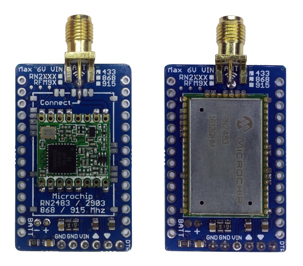
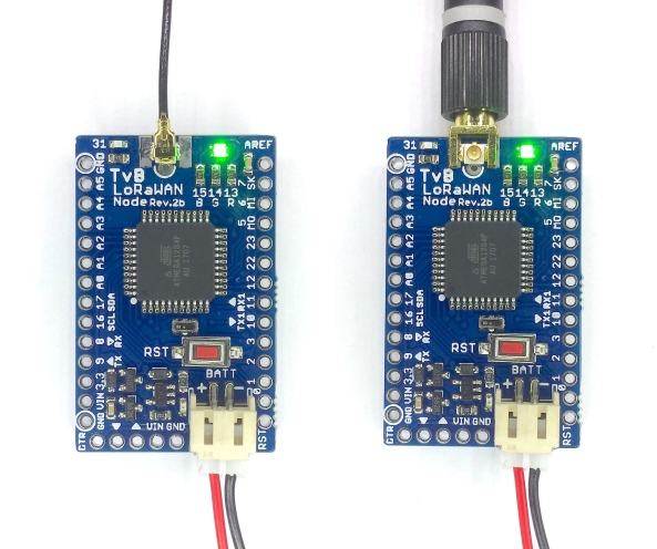
After the great succes with the default LoRaWAN Node I really wanted to design an inexpensive Node with an build-in antenna for small LoRaWAN use cases.

side_picture_export

Good antenna’s are expensive!

When it comes to antenna’s, one thing is certain: Good antenna’s aren’t cheap.
I guess we all bought those crappy cheap antennas in the past to find out they are not designed for that frequency or don’t work at all..

Choosing for an onboard antenna makes you node compact an even more low cost. You don’t need those antenna connectors, cables and antennas. Any PCB based antenna won’t have the same range as an “real” antenna but the goal is to get about half the distance.

The new antenna: Ceramic chip or custom antenna design?

For an onboard antenna you can easily chose an ceramic chip antenna for the desired frequency. There are a lot of these antenna chips available and it doesn’t take a lot of experience to use them. They can save you most space on your PCB.

Ceramic chip antennas

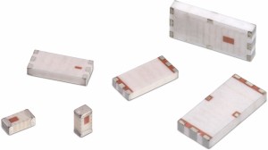
Most of these chips are affordable but I decided to not use any chip antenna and design my own antenna!
Making the ideal antenna takes some time and a certain knowledge in electronics, HF and antenna’s. This includes everything from calculations, simulations, designing, prototyping, measuring, and modifying before the results are really satisfying.
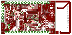
The design

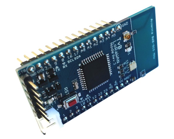
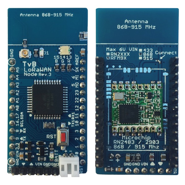
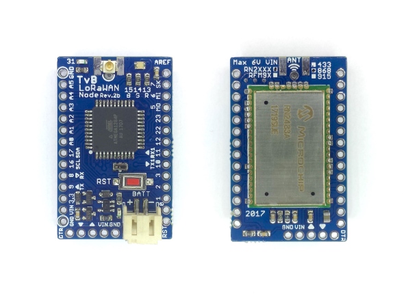
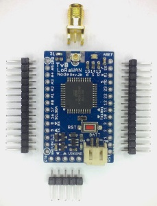
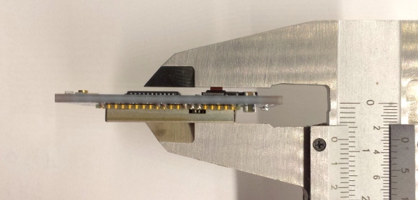
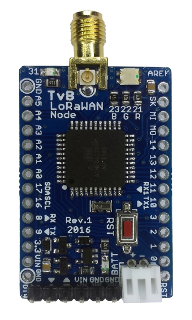
For the new Node I didn’t want to change anything from my existing proven “TvB LoRaWAN Node”. This limits the available space to a width of 26mm for the antenna.

Here’s the initial design I came up with:

pcb-design

Verifying, measuring, optimizing and testing the antenna design took a while but the result was worth it.
The final measurements concluded that the center frequency of the antenna design is about 20 MHz’s off the 868 MHz goal. So we’re not there yet.

That’s great, but what does that mean?

An design update, mostly based on measurements.
The most important thing of any antenna is the range. To get the maximum out of your antenna the center frequency has to match the desired frequency as best possible. This point will transmit the most RF energy resulting in a better range.

You can’t compare a lab measurement with an real world test so you always have to verify the range. After assembling the first prototype it’s time to put it to the test!

top_view_battery_export

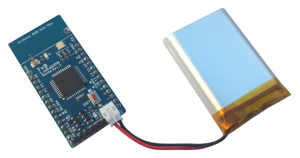
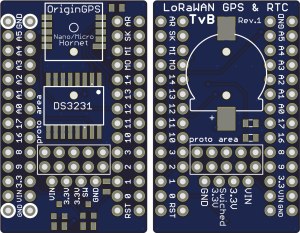
For range testing I simply hooked up an GPS module to the battery powered Node.
The Node receives a GPS location form the GPS module and transmits it’s location every 15 seconds over LoRaWAN.

When a message is received on the gateway(‘s) you can simply plot the distance between transmitter and receiver.
For testing purposes I used an RFM95W LoRa module from HopeRF, with the default LoRaWAN settings (SF12). That’s it!

The range, what can you expect from internal, microstrip antenna’s?

I didn’t expect much from a small antenna but I guess I’m wrong. LoRaWAN is a very impressive technology that’s able to send messages over many and many km’s.

Practical measurements with a regular node (default λ/4 antenna for 868 MHz) results in maximum ranges up to 20km and more in the ideal situation.
I guessed the range of the internal antenna would be around a couple of km’s with a maximum range of 5 km’s. Everything beyond that would be great.

Range test, the first test-drive

I didn’t expect much from the first range test-drive. In the message log I was hoping to find a couple of messages but there much more received messages than “just a couple”. Meaning only one thing: The Node works!

Analyzing all location data showed distances up to a whopping 9 km from inside the car!
All other range measurements confirmed this first impression.

Conclusion

I may decide that this node has a guaranteed range of about 5 km for LoRaWAN use cases in real world. Almost all messages within that radius are well received on the gateways.

The test data also showed that the antenna acts as a directional antenna, performing a little bit better in the one direction than the other. Unlike an default λ/4 antenna that radiates the same amount of energy in all directions.
The node has to be used with the antenna pointing upwards for the best results.
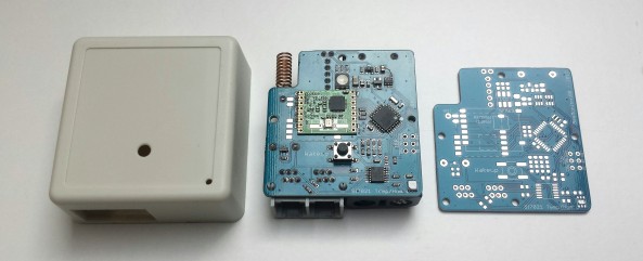
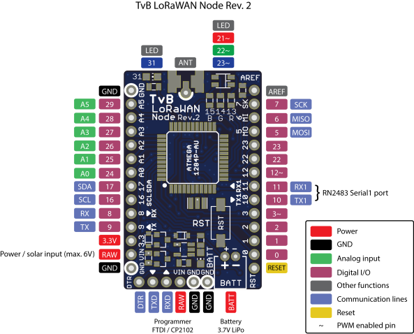
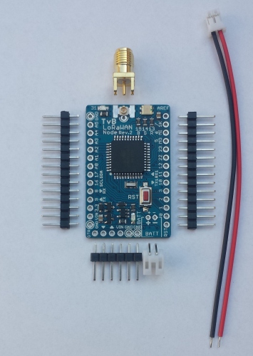
Hardware details

top_bottom_combined

Work in progress

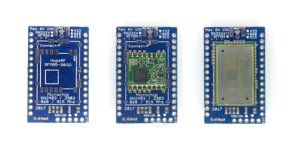
There’s still some space for improvement. Because the used frequency in Europe is 868MHz I’ve optimized the design for that exact frequency.
Based on the measurements on the first design I made a couple of different modified versions. The good news: some of them perform better than the first version because they have more gain on 868MHz.

TvB LoRaWAN Node

I’m getting a lot of response and technical questions about the new LoRaWAN Node.
With this post I hope to give a better overview of the Node hardware and features for those interested in building there own.

overview-node-shield

TvB LoRaWAN Node with RFM95W or RN2483 & Proto Shield

The LoRaWAN Node is a compact, universal and affordable LoRaWAN Node with a powerful Arduino compatible Atmel microcontroller.

Features:

Microcontroller
  • Atmel Atmega1284P (Arduino compatible)
Size
  • 40 x 25 mm
Operating voltage
  • 3.3V (onboard regulator)
I/O pins
  • 24 available pins (Digital I/O, Analog input, PWM, UART, SPI & I2C)
Flash memory
  • 128 KB (4x more than Arduino Uno)
SRAM
  • 16 KB (8x more than Arduino Uno)
EEPROM
  • 4 KB (4x more than Arduino Uno)
Clock
  • 8 MHz
Power
  • 5V USB power
  • Single cell 3.7V LiPo battery
Charging
  • (Solar) Charge controller IC with status LED, up to 500mA charge current (max. 6V input)
LED
  • RGB LED + extra blue LED
Supported LoRaWAN modules
  • HopeRF RFM9X
  • Microchip RN2483 / RN2903 (High-band only)
Antenna
  • U.FL and/or SMA connector
Programming
  • FTDI programming header for USB to Serial converter
Extra
  • Default JST 2.0 battery connector
  • Buid-in battery voltage divider for measuring battery state
  • Onboard reset switch
  • Breadboard compatible headers
The LoRaWAN Node is only 7.5 mm thick when used with an RN2483 LoRaWAN module.

The LoRaWAN Node is only 7.5 mm thick when used with an RN2483 LoRaWAN module (without JST battery connector).

Pinout:

tvb-lorawan-node-rev-2-pinout
Because I like to use different LoRaWAN modules depending on the project I’ve added support for the 2 most popular LoRaWAN modules:

  • TvB LoRaWAN Node – RFM95W
  • TvB LoRaWAN Node – RN2483 (LoRaWAN Certified)

Without any hardware modifications I can use one of these 2 modules.
The practical range of both modules is the same, the only big difference is the missing LoRAWAN certification for the RFM95W.


Here a more detailed picture of the Node with headers, SMA antenna connector and the JST battery connector to power the board (the power cable is not included).

tvb-lorawan-node-rev2

TvB LoRaWAN Node with accessories

To make my applications more “Plug & Play” I made myself a great gadget: The “Proto Shield”.
It’s designed to fit on the node to create prototyping space.
It even has an extra mosfet load-switch circuit with LED indication to power ON/OFF external circuits! Great, isn’t it?

tvb-proto-shield-rev2

TvB Proto Shield with female headers

Want to know more? Get in touch here

Please note: This hardware is not for sale, neither is the schematic or design files.
The developed hardware / software is not open source.

LoRaWAN Node Shields

My new LoRaWAN node also comes with additional shields to realize the most crazy projects. They are available for order with the any version of the node.

All shields are the same size as the node and are connected with two regular 14 pin headers.
At the moment I developed 3 shields:

  • Proto shield
    • Proto area
    • Load switching mosfet circuit controlled by digital pin to power on/off external electronics. With power-on LED.

TvB LoRaWAN Proto Shield Rev.2 - Preview

  • RTC shield
    • DS3231 with 3V backup battery.
      The DS3231 also has a programmable interrupt output to wake up the LoRaWAN node every X seconds, minutes, hours, …
    • Small proto area
    • Load switching mosfet circuit controlled by digital pin to power on/off external electronics. With power-on LED.

TvB LoRaWAN Node RTC Shield Rev.1 - Preview

  • RTC & GPS shield
    • DS3231 with battery backup
    • Ultra small GPS module (OriginGPS Nano/Micro Hornet) with onboard, buildin GPS/GLONASS antenna
    • Small proto area
    • Load switching mosfet circuit controlled by digital pin to power on/off external electronics

TvB LoRaWAN Node RTC + GPS Shield Rev.1 - Preview

The RTC/GPS node is only available without GPS module

The new LoRaWAN Node is alive!


Last week I found some time to assemble and test my new LoRaWAN Node and here’s the result.

TvB LoRaWAN Node - Front viewFeatures of the new board:

  • Only 25 mm x 40 mm!
  • Low power Atmega1284p microcontroller (Arduino compatible, incl. bootloader & library)
  • Standard JST battery connector
  • Onboard single cell li-ion / polymer battery charger with charge status LED (charging from USB programmer or solar panel)
  • Onboard 3.3V LDO regulator with protection circuit
  • Battery voltage measurement
  • Breadboard compatible headers
  • Reset button
  • RGB led
  • Extra blue led for RX/TX activity (default color, can be changed on request)
  • Full FTDI programming header
  • U.FL & SMA antenna connectors
  • LoRaWAN:
    • Support for Microchip RN2483 & RN2903 LoRaWAN modules
    • Support for HopeRF RFM9X LoRa modules

The best part of this module is that the LoRaWAN module can be chosen.
I’ve added support for both modules on the same board!
TvB LoRaWAN Node - Back view

This Node is a perfect starting base for most of my LoRaWAN projects. It’s the same size as the recent Sodaq LoRaONE and a whole lot cheaper! (But there’s no fancy GPS or accelerometer).

More details, info, .. can be found in this new post: eth0maz.wordpress.com/2016/09/26/tvb-lorawan-node/