The MCP23017 I/O Expander: Instantly
Increase your I/O with 16 Fully Bidirectional I/O pins. Need more? Just
add extra chips, on the same I2C interface; Up to 128 Extra I/O pins!
Maybe you should really use MCP23S17 - GPA7 and GPB7 have a problem!
The MCP23017 is an I2C port expansion chip that:
Adds 16 I/O pins per chip.
Uses only Two I2C pins.
Has fully bidirectional I/O pins, with pullups.
Has interrupt ability (a separate pin from each chip using wire-or).
Allows a total of 8 chips for 128 I/O pins - change the I2C address for each chip.
Still uses only Two I2C pins even for 128I/O pins!
You can use the chip to increase the number of I/O pins for any
microcontroller that can communicate using an I2C
interface.
Warning: The latest
datasheet - Revision D (June 2022) - says you must not use GPA7
& GPB7 as inputs pins - even though you can set them as inputs!
The data sheet does not say why but the microchip site has more details; summarised here:
If the pin voltagechanges while these pins are being read during transmission
of a bit, the SDA signal can be corrupted. This can cause bus host
malfunction. The relevant pins in the library used below are P7 and P15.
So you may get reasonable operation with these pins as inputs but there is a chance it could go wrong!
See the highlights section (top of pdf) Rev.c 2022 datasheet. The only other place this is mentioned in the datasheet is in 3.5.1 I/O DIRECTION REGISTER.
Note that it specifically says MCP23017, and it looks like an I2C specific problem.
This data sheet is an MCP23017/MCP23S17 combined information - the SPI version does not have this problem.
This page shows you how to control the device
for driving LEDs and reading button presses but you can use it anywhere
that you need more general purpose inputs or outputs
pin.
It also shows you exactly
how to use
interrupts, which is very tricky, as there are some unexpected problems (solved here)
when using existing Arduino code.
Note: The I/O pins are virtually identical to standard microcontroller pins. They even have programmable pullups for each pin!
The MCP23017 easily interfaces with any microcontroller, providing an
extra 16 I/O pins (that are just as capable normal I/O pins) using the simple I2C interface. Its interrupt capability
gives you full control for efficient monitoring and response.
For even
more I/O expansion, simply cascade multiple MCP23017 devices (using the
same I2C pins!), increasing your total I/O to a maximum of 128 pins
(using 8 devices on the same I2C bus).
The rest of this page shows you how to use the MCP23017 with Arduino in
detail.
Note: For a multiple 23017 interrupt tutorial for this chip see
here.
For some applications it could be a bit over the top; For example if you
only want to control outputs a 74HC595 would be cheaper.
The IC2 version operates at 100kHz, 400kHz and 1.7MHz speeds. It also
operates from 1.8V to 5.5V.
Having interrupt outputs is one of the most important features of the
MCP23017, since the microcontroller does not have to continuously poll the
device to detect an input change. Instead an interrupt service routine can be
used to react quickly to an input change on any pin e.g. a key press etc.
Image created using Frizting
Note: In the above diagram the 4th pin from
the right is pulled high (pin 18) - the chip reset pin. This was done
for open drain control that is not needed in this instance - you don't
need a
resistor here at all - just connect it to Vcc (5V).
The MCP23017 has internal pullups for each input pin (configurable) so there is
no need to add external pull up resistors for inputs such as push buttons
etc.
The device also has provision for 3 address inputs so you can add a total of
8 devices onto the same I2C bus which gives you 128 new I/o pins only requiring
two microcontroller I2C pins for control.
An alternative device is the MCP23S17 which is uses the SPI
interface that can operate at 10MHz (a lot faster than the I2C version). This
SPI device has the same number and arrangement of pins, but uses two unused
(I2C) pins to implement the SPI interface. In all other respects it operates
the same as the MCP23017.
To make life even easier each GPIO input pin can be configured with an
internal pullup (~100k) and that means you won't have to wire up external pull
up resistors for keyboard input. You can also mix and match inputs and outputs
the same as any standard microcontroller 8 bit port.
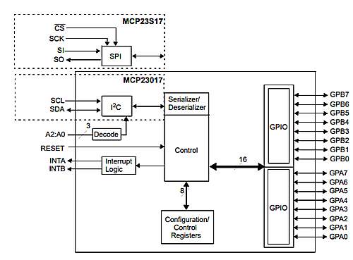
MCP23017 Block diagram
This diagram from the datasheet shows the main blocks within the
chip. It also shows the difference between the I2C and SPI interfaces
(The MCP23S17 is the SPI version chip). In the SPI interaface an extra
control pin is required for the Chip Select line (CS), and for the I2C
version this pin is set to N.C. (Pin 11).
* This is an
unusual parameter specification. and relates to the fact that there must be a
asymmetrical architecture in the chip that can accept only the specified
current. The overall sink current is 150mA Vss and overall source current is
125mA.
Sink current is the current flowing (from an external circuit) when a pin is
taken low. Source current is the flowing (to an external circuit) when a pin is taken
high.
The "Current Max out of Vss" is the sum of all sinking currents.
The "Current Max into Vdd" is the sum of all sourcing currents.
MCP23017 Datasheet
Download the Rev.c 2022 datasheet is here. One of the main changes is that GPA7 and GPB7 have to be outputs.
The 23017 has three input pins to allow you to set a different address for
each attached MCP23017. Addresses available are specified in the I2C control
byte and each device is selected by the I2C sequence below:
The above corresponds to a hardware address for the three lines A0, A1, A2
corresponding to the input pin values at the IC. You must set the value of
these hardware inputs as 0V or (high) volts and not leave them floating
otherwise they will get random values from electrical noise and the chip will
do nothing!
The four left most bits are fixed a 0100 (specified by a consortium who
doles out address ranges to manufacturers).
So the MCP23017 I2C address range is 32 decimal to 37 decimal or 0x20 to
0x27 for the MCP23017.
Note: The address range allows 3 bits and
this means a maximum of eight MCP23017 devices can be attached
to any single I2C bus. If you want more you would need to
either use a second I2C bus or bit bang some pins to simulate one, or do
something clever with more hardware i.e. another microcontroller intercepting
unused I2C addresses and converting an them to control the extra
MCP23017s.
MCP23017 LED Driver
The above specification shows that the device is quite capable of driving
current to LEDs however there are 16 outputs so the maximum output current for
the whole device has to be shared by all the LEDs.
Warning: Maximum total current chip is 150mA,
and the maximum for an individual pin is 25mA.
If you drive 16 LEDs then it will be 150mA/16 =9.38mA per GPIO pin (MAX).
This also assumes that you are turning the LED on when it is driven low. Note:
Choose a lower current to keep within limits.
Remember that different LED colours have a different forward voltage drop
when driven (this is constant due to how a diode behaves) so to control the
forward current you have to specify the correct current limiting resistor for
the voltage source used.
If you are turning it on when driven high then the equation is
125/16mA=7.8mA (MAX). Note: Choose a lower current to keep within limits.
TIP: If your MCP23017 is getting hot, then
look at the overall output current from the chip by calculating the current
from each pin and then adding up these results. If it is more than 150mA then
reduce the current by increasing the current limiting resistors for each
pin.
Obviously reducing the number of outputs in use will allow increasing
current up to a maximum of 25mA per pin but then you could drive only 6 pins at
full current! (150mA/25mA=6). You must always to keep the maximum overall
output current for the chip within the 150mA limit otherwise the chip gets hot
and will probably fail.
The fact that the MCP23017 gets hot is not a problem if you keep the maximum
overall current consumption to 150mA. You should look at the data sheet for the
maximum temperature allowed, and measure the chip temperature at its surface.
The data sheet, usually, I did not look in this case, also specifies a
de-rating parameter (or graph) so that if used within a hot enclosure (or any
environment) you have to reduce the maximum current consumed!
MCP23017 Non interrupt
registers
IODIR I/O direction register
For controlling I/O direction of each pin, register IODIR (A/B) lets you set
the pin to an output when a zero is written and to an input when a '1' is
written to the register bit. This is the same scheme for most microcontrollers
- the key is to remember that zero ('0') equates to the 'O' in Output.
GPPU Pullup register
Setting a bit high sets the pullup active for the corresponding I/O pin.
OLAT Output Latch register
This is exactly the same as the I/O port in 18F series PIC chips where you
can read back the "desired" output of a port pin whether or not the actual
state of that pin is reached. i.e. consider a strong current LED attached to
the pin - it is easily possible to pull down the output voltage at the pin to
below the logic threshold i.e. you would read back a zero if reading from the
pin itself when in fact it should be a one. Reading the OLAT register bit
returns a 'one' as you would expect from a software engineering point of
view.
IPOL pin inversion register
The IPOL(A/B) register allows you to selectively invert any input pin. This
reduces the glue logic needed to interface other devices to the MCP23017 since
you won't need to add inverter logic chips to get the correct signal polarity
into the MCP23017.
It is also very handy for getting the signals the right way up e.g. it is
common to use a pull up resistor for an input so when a user presses an input
key the voltage input is zero, so in software you have to remember to test for
zero.
Using the MCP23017 you could invert that input and test for a 1 (in my mind
a key press is more equivalent to an on state i.e. a '1') however I use pullups
all the time (and uCs in general use internal pullups when enabled) so have to
put up with a zero as 'pressed'. Using this device would allow you to correct
this easily.
Note: The reason that active low signals are used everywhere
is a historical one: TTL (Transistor Transistor Logic) devices draw more power
in the active low state due to the internal circuitry, and it was important to
reduce unnecessary power consumption - therefore signals that are inactive most
of the time e.g. a chip select signal - were defined to be high. With CMOS
devices either state causes the same power usage so it now does not matter -
however active low is used because everyone uses it now and used it in the
past.
SEQOP polling mode : register bit : (Within
IOCON register)
If you have a design that has critical interrupt code e.g. for performing a
timing critical measurement you may not want non critical inputs to generate an
interrupt i.e. you reserve the interrupt for the most important input data.
In this case, it may make more sense to allow polling of some of the device
inputs. To facilitate this "Byte mode" is provided. In this mode you can read
the same set of GPIOs using clocks but not needling to provide other control
information. i.e. it stays on the same set of GPIO bits, and you can
continuously read it without the register address updating itself. In non byte
mode you either have to set the address you read from (A or B bank) as control
input data.
Note: Interrupt registers are discussed later on here.
Software Library and versions
Arduino IDE Version
Version : 1.8.3
Adafruit library
MCP23017 library for aruduino
Adafruit MCP23017 Library 1.0.3
Note: This library depends on Adafruit BUSIO so manually install that or accept the library manager doing it for you.
This is easily installed from the Arduino IDE.
If you do not see the library as an entry when you click the menus then
install the library as follows:
Sketch-->Include Library
Then select manage libraries :
Sketch-->Include Library -->Manage
Libraries...
Search for and install <lib name> using the "Filter Your Search"
form.
Library Operation
Pin definition for MCP23017
library
Note: In the library pins are labelled from 0 to 15 where:
pin 0 is bit 0 of port A
pin 7 is bit 7 of port A
pin 8 is bit 0 of port B
pin 15 is bit 7 of port B
You
can see that the "Arduino type" pin numbering does not follow the usual
chip numbering convention where lower numbers start at the top left and increment anti-clockwise around the chip!
MCP23017 I/O control
functions
Single Bit I/O
Similar member functions to the pin controls on the Arduino are used to
control the MCP23017 pins:
mcp.pinMode(0, OUTPUT);
mcp.digitalWrite(0,HIGH);
mcp.digitalRead(0);
Connections
Simple Netlist connections
The following netlist and diagram show you how connecting the MCP23017 to
the Arduino is very simple.
Connect pin #12 of the expander to Arduino Analog 5 (i2c clock)
Connect pin #13 of the expander to Arduino Analog 4 (i2c data)
Connect pin #19 of the expander to Arduino pin 3 (interrupt input).
Connect pins #15, 16 and 17 of the expander to Arduino ground (address
selection)
Connect pin #9 of the expander to Arduino 5V (power)
Connect pin #10 of the expander to Arduino ground (common ground)
Connect pin #18 of the expander through a ~10kohm resistor to 5V (reset pin,
active low).
Connect pin #28 of the expander to +ve end of an LED then to a ~1kohm
resistor to GND (MCP_LED1) or wire directly to 5V. I must have been
thinking of open drain controls - you don't need the resistor.
Connect pin #26 of the expander to +ve end of an LED then to a ~1kohm
resistor to GND (MCP_LEDTOG1).
Connect pin #4 of the expander to +ve end of an LED then to a ~1kohm resistor
to GND (MCP_LEDTOG2).
Connect pin #1 of the expander to a normally open push button that then
connects to GND (MCP_INPUTPIN).
Note: pullups are enabled for I2C pins in the "Wire" library
so are not shown in the above circuit connection or layout (below). They are
high value (probably 50k~100k), so for a faster rising edge on I2C signals use
lower value physical pullup resistors that will override the high value.
Fritzing Layout : MCP23017 Circuit
Image created using Frizting
Arduino MCP23017 Examples Code
Example 1 Basic operation
This example shows three LEDs on different ports of the MCP23017, with two
on port A (Green and Red). Two LEDs are alternately flashed (Red ones) while
the third shows the state of the input on GPB0 i.e GPB0 is read by the Arduino
and then the Green LED is updated. This shows independent control of individual
port bits i.e. while flashing the red LEDs the button is read and the green one
is updated.
It serves to demonstrate how interrupts will be useful (see next example for
interrupt code). Try pushing the button and releasing it quickly - usually the
output green LED does not change state immediately - you may find the key press
is not even detected!.
The following example shows using Arduino and the mcp23017 library.
Warning: Later versions of the library Change code so it breaks:
Now using Adafruit MCP23017 Version 2.3.0 // USE This library.
Original version: Adafruit MCP23017 Library 1.0.3
Change from:
#include <Adafruit_MCP23017.h>
To: #include <Adafruit_MCP23X17.h> // USE THIS in your code.
Also the instantiation changes from:
Adafruit_MCP23017 mcp;
To: Adafruit_MCP23X17
mcp;
// USE THIS in your code.
AND
member function mcp.begin()
To: mcp.begin_I2C(); // USE THIS in your code.
Talk about breaking code - it should at least define mpc.begin() as well!!!!!!!
...and for member function pinMode() (of library Adafruit_MCP23017) :
mcp.pinMode(BUTTON_PIN, INPUT_PULLUP);
This function now works as expected for pullup setting, and it does make
sense as MCP23017 code now matches Arduino pinMode operation.
The example code below has been updated for Version 2.3.0 Library. If
you use code written for the older library version you will need to make
changes (as above) to get it to work.
// Toggle LEDs and detect keypress.
//
// Example code showing slow reaction of 'button'
// LED to keypress. Leading into why interrupts
// are useful (See next example).
//
// Copyright : John Main
// Free for non commercial use.
#include <Wire.h>
#include <Adafruit_MCP23X17.h>
#define MCP_LED1 7
#define MCP_INPUTPIN 8
#define MCP_LEDTOG1 11
#define MCP_LEDTOG2 4
Adafruit_MCP23X17mcp;
voidsetup(){
mcp.begin_I2C();// Default device address 0
mcp.pinMode(MCP_LEDTOG1,OUTPUT);// Toggle LED 1
mcp.pinMode(MCP_LEDTOG2,OUTPUT);// Toggle LED 2
mcp.pinMode(MCP_LED1,OUTPUT);// LED output
mcp.digitalWrite(MCP_LED1,HIGH);
mcp.pinMode(MCP_INPUTPIN,INPUT_PULLUP);// Button i/p to GND
}
// Alternate LEDTOG1 and LEDTOG2.
// Transfer pin input to LED1.
voidloop(){
delay(300);
mcp.digitalWrite(MCP_LEDTOG1,HIGH);
mcp.digitalWrite(MCP_LEDTOG2,LOW);
delay(300);
mcp.digitalWrite(MCP_LEDTOG1,LOW);
mcp.digitalWrite(MCP_LEDTOG2,HIGH);
// Transfer input pin state to LED1
if(mcp.digitalRead(MCP_INPUTPIN)){
mcp.digitalWrite(MCP_LED1,HIGH);
}else{
mcp.digitalWrite(MCP_LED1,LOW);
}
}
Here is the code (below) that I wanted to use and when you look at it, it
appears perfectly reasonable.
Note: The example code below is show for
educational purposes and does not work
correctly (See below for why this is the case).
The following code has three standard functions:
setup()
isr()
loop()
The setup function initialises the ports while loop function toggles some
leds and the isr reacts to a button press (it should do but the code fails).
Note: This code hangs waiting for interrupts see next code
example for the solution.
// MCP23017 Example: Unexpected Interrupt failure.
//
// This code sends an interrupt from the MCP23017
// to an Arduino external interrupt pin when an
// MCP23017 input button press is detected.
// At the same time MCP LEDs are toggled on button
// release. THIS CODE FAILS FOR A VERY SUBTLE REASON.
//
// Copyright : John Main
// Free for non commercial use.
#include<Wire.h>
#include<Adafruit_MCP23017.h>
// MCP23017 setup
#defineMCP_LED17
#defineMCP_INPUTPIN8
#defineMCP_LEDTOG111
#defineMCP_LEDTOG24
// Register bits
#defineMCP_INT_MIRRORtrue// Mirror inta to intb.
#defineMCP_INT_ODRfalse// Open drain.
// Arduino pins
#defineINTPIN3// Interrupt on this Arduino Uno pin.
volatileuint16_tdmy;// Dummy for use within interrupt.
Adafruit_MCP23017mcp;
voidsetup(){
mcp.begin();// use default address 0
pinMode(INTPIN,INPUT);
mcp.pinMode(MCP_LEDTOG1,OUTPUT);// Toggle LED 1
mcp.pinMode(MCP_LEDTOG2,OUTPUT);// Toggle LED 2
mcp.pinMode(MCP_LED1,OUTPUT);// LED output
mcp.digitalWrite(MCP_LED1,LOW);
// This Input pin provides the interrupt source.
mcp.pinMode(MCP_INPUTPIN,INPUT);// Button i/p to GND
mcp.pullUp(MCP_INPUTPIN,HIGH);// Puled high ~100k
// On interrupt, polariy is set HIGH/LOW (last parameter).
mcp.setupInterrupts(MCP_INT_MIRROR,MCP_INT_ODR,LOW);
mcp.setupInterruptPin(MCP_INPUTPIN,FALLING);
mcp.readGPIOAB();// Initialise for interrupts.
// Enable interrupts - This is the Arduino interrupt control.
attachInterrupt(digitalPinToInterrupt(INTPIN),isr,FALLING);
}
// The interrupt routine handles MCP_LED1
// This is the button press since this is the only active interrupt.
voidisr(){
staticuint8_tledState=0;
// Debounce. Slow I2C: extra debounce between interrupts anyway.
// Can not use delay() in interrupt code.
delayMicroseconds(1000);dmy=mcp.readGPIOAB();
if(ledState){
mcp.digitalWrite(MCP_LED1,LOW);
}else{
mcp.digitalWrite(MCP_LED1,HIGH);
}
ledState=!ledState;
}
//////////////////////////////////////////////
voidloop(){delay(300);
mcp.digitalWrite(MCP_LEDTOG1,HIGH);
mcp.digitalWrite(MCP_LEDTOG2,LOW);
delay(300);
mcp.digitalWrite(MCP_LEDTOG1,LOW);
mcp.digitalWrite(MCP_LEDTOG2,HIGH);
}
Example 3 Interrupt Example
This Arduino MCP23017 Interrupt Example code shows you exactly how to use
and connect an external interrupt pin and make interrupts work correctly. As
you saw in the previous example - you can not just use the Arduino template
code because there is a subtle problem involved. This example explains the
problem and solves it.
The requirement for operating interrupts is that to clear an interrupt state
you have to read from either INTCAP (interrupt data captured) or GPIO.
Important: To clear interrupts you must read back data from
either INTCAP(A/B) or GPIO(A/B).
In the previous code (Example 2), GPIO is read inside the isr() function in
order to reset the MCP23017 interrupts. However the code hangs at that
point!
If you look in the library code you won't see any reason for it at all.
Looking a little deeper reveals the culprit - which is the "Wire" library.
In this library a hardware interrupt from the I2C module is in use. Since
interrupts are disabled when the callback function is executed the code hangs
waiting for the I2C interrupt that is never actioned.
That means you can't use the mcp23017 library code to clear the interrupts
using the "read GPIO" function (unless you use a special technique - see below)
because the Wire library never completes!
The key is to allow other interrupts in the current isr() routine but not
those that would restart the current isr i.e. stop the MCP23017 interrupts
temporarily. Arduino functions detatchInterrupt(), attachInterrupt(),
interrupts(), noInterrupts() are used to achieve this.
Note: Accessing the MCP23017 via I2C takes a while so debounce
is probably accounted for by the time that it takes to refresh the I/O
expander.
It is worth studying the code, as the way this works is fairly complex i.e.
allowing interrupts from within an already operating interrupt triggered
routine.
// MCP23017 Example: Interrupt operation.
//
// This code sends an interrupt from the MCP23017
// to an Arduino external interrupt pin when an
// MCP23017 input button press is detected.
// At the same time MCP LEDs are toggled on button
// release.
//
// Copyright : John Main
// Free for non commercial use.
#include<Wire.h>
#include<Adafruit_MCP23017.h>
// MCP23017 setup
#defineMCP_LED17
#defineMCP_INPUTPIN8
#defineMCP_INPUTPIN210
#defineMCP_LEDTOG111
#defineMCP_LEDTOG24
// Register bits
#defineMCP_INT_MIRRORtrue// Mirror inta to intb.
#defineMCP_INT_ODRfalse// Open drain.
// Arduino pins
#defineINTPIN3// Interrupt on this Arduino Uno pin.
#definecontrolArduioIntattachInterrupt(digitalPinToInterrupt(INTPIN),isr,FALLING)
Adafruit_MCP23017mcp;
//////////////////////////////////////////////
voidsetup(){
mcp.begin();// use default address 0
pinMode(INTPIN,INPUT);
mcp.pinMode(MCP_LEDTOG1,OUTPUT);// Toggle LED 1
mcp.pinMode(MCP_LEDTOG2,OUTPUT);// Toggle LED 2
mcp.pinMode(MCP_LED1,OUTPUT);// LED output
mcp.digitalWrite(MCP_LED1,LOW);
// This Input pin provides the interrupt source.
mcp.pinMode(MCP_INPUTPIN,INPUT);// Button i/p to GND
mcp.pullUp(MCP_INPUTPIN,HIGH);// Puled high ~100k
// Show a different value for interrupt capture data register = debug.
mcp.pinMode(MCP_INPUTPIN2,INPUT);// Button i/p to GND
mcp.pullUp(MCP_INPUTPIN2,HIGH);// Puled high ~100k
// On interrupt, polariy is set HIGH/LOW (last parameter).
mcp.setupInterrupts(MCP_INT_MIRROR,MCP_INT_ODR,LOW);// The mcp output interrupt pin.
mcp.setupInterruptPin(MCP_INPUTPIN,CHANGE);// The mcp action that causes an interrupt.
mcp.setupInterruptPin(MCP_INPUTPIN2,CHANGE);// No button connected, see effect on code=none.
mcp.digitalWrite(MCP_LED1,LOW);
mcp.readGPIOAB();// Initialise for interrupts.
controlArduioInt;// Enable Arduino interrupt control.
}
//////////////////////////////////////////////
// The interrupt routine handles LED1
// This is the button press since this is the only active interrupt.
voidisr(){
uint8_tp,v;
staticuint16_tledState=0;
noInterrupts();
// Debounce. Slow I2C: extra debounce between interrupts anyway.
// Can not use delay() in interrupt code.
delayMicroseconds(1000);// Stop interrupts from external pin.
detachInterrupt(digitalPinToInterrupt(INTPIN));
interrupts();// re-start interrupts for mcp
p=mcp.getLastInterruptPin();
// This one resets the interrupt state as it reads from reg INTCAPA(B).
v=mcp.getLastInterruptPinValue();
// Here either the button has been pushed or released.
if(p==MCP_INPUTPIN&&v==1){// Test for release - pin pulled high
if(ledState){
mcp.digitalWrite(MCP_LED1,LOW);
}else{
mcp.digitalWrite(MCP_LED1,HIGH);
}
ledState=!ledState;
}
controlArduioInt;// Reinstate interrupts from external pin.
}
//////////////////////////////////////////////
voidloop(){
delay(300);
mcp.digitalWrite(MCP_LEDTOG1,HIGH);
mcp.digitalWrite(MCP_LEDTOG2,LOW);
delay(300);
mcp.digitalWrite(MCP_LEDTOG1,LOW);
mcp.digitalWrite(MCP_LEDTOG2,HIGH);
}
Warning: The arduino library cannot cope with more than one
interrupt source due to the way the library code is written (which fits to the
Arduino philosophy of "abstracted pin operation"). Since code is pin-centric
within Arduino the first interrupt flag value that is found active (in the INTF
register) returns that pin value - any more are ignored. For multiple interrupt
sources you will need to write your own functions that are not pin-based.
MCP23017 Interrupt registers
The interrupt are comprehensive in this
device, and consequently require a large amount of control registers. The
following information allows you to easily understand and control the MCP23017
when using interrupt operation.
The device is split into two sets of 8 GPIO registers and each set can have
a separate interrupt associated with it (INTA and INTB outputs).
These are the registers associated with interrupts in the MCP23017:
GPINTEN
INTCON
DEFVAL
IOCON.MIRROR (a bit in the IOCON register)
IOCON.INTPOL (a bit in the IOCON register)
IOCON.ODR (a bit in the IOCON register)
INTCAP
INTF
Add an A or B to the name for control of a specific register set.
Note: Register names may sound similar to PIC device names since the chip
was also designed by MicroChip.
MIRROR register bit : (Within IOCON
register)
The control bit MIRROR wire ORs INTA and INTB together if set - that means
any interrupt condition on any port will cause both INTA and INTB to be
activated. When not set you have two separate interrupt outputs: INTA and INTB
each associated with the A or B register.
INTPOL register bit : (Within IOCON
register)
If set means the interrupt output is active high.
ODR register bit : (Within IOCON
register)
If set means the interrupt pin is open drain (overrides INTPOL).
INTCON register
INTCON controls how interrupt conditions are detected as below:
There are two ways of detecting interrupt states for a specific register
bit:
Input Pin change, (A specific INTCON bit associated with a pin is 0) -
This is the default.
Input pin change compared to defined value in DEFVAL, (A specific INTCON
bit associated with a pin is 1)
In the first case an interrupt is generated if the new pin value is
different to the old pin value.
In the second case an interrupt is generated if the new pin value is
different to the stored default value (DEFVAL).
DEFVAL register
Sets the default value of a pin which is the inactive input interrupt
state.
Say you have two interrupt sources e.g. an active low alarm (ALRM) and an
active high sensor (SENS) and you want either of these to cause an interrupt.
Using the DEFVAL register you would set:
the DEFVAL value for ALRM to high,
the DEFVAL value for SENS to low.
Any signal opposite to the DEFVAL value would trigger an interrupt. So if
the ALRM signal goes to 0V an interrupt would be triggered, and if the SENS
signal goes to 5V an interrupt would be triggered.
This saves having to put inverter chips all over the place to get the right
signal polarity. You would also enable the corresponding INTCON and GPINTEN
bits corresponding to the bit positions in the register for the pins used as
interrupts.
GPINTEN register
You may have some pins as LED outputs so you won't want them causing an
interrupt or you may have some inputs that you only need to poll occasionally.
GPINTEN is the register that enables each bit of the register to act as an
interrupt on change pin (IOC). Using GPINTEN, you enable specific input pins as
interrupts by setting the corresponding bit high.
INTA and INTB registers
The chip also allows ultimate configuration of the output states of INTA and
INTB. This is quite unusual as chips usually have a fixed output state that you
have to add glue logic around to get the right signal polarity.
For each INTA and INTB you can set the output as:
Active low
Active high
Open Drain
These can be controlled from within the IOCON register.
Note: Only the INTA and INTB pins on the MCP23017 are open
drain (if you set them to be open drain).
INTF Interrupt Flag register
The INTF register is the interrupt flag register and tells you which
interrupt input cause the current interrupt trigger. When a bit is set in this
register (that is enabled for interrupts) the associated pin caused the
interrupt.
INTCAP Interrupt Data
Capture register
A further feature of the chip is that the value of the register is captured
when an interrupt is triggered. INTCAP stores the input state of the input pins
when the interrupt occurred. Any further interrupt conditions will not cause an
interrupt until either INTCAP or GPIO is read.
Interrupt Operation
During the process of reacting to the INTF flag your code will likely take
too long to read the interrupt data registers (remember this is a serial
interface device so it takes time to get the serial data back from the
MCP23017).
Even though it is on a fast serial interface you will have to set
some command register addresses which are themselves serial output data bursts.
You could have missed any changes from when the interrupt fired to the time
that you get around to reading back exactly which interrupt caused INTF change!
To avoid this situation, INTCAP preserves that interrupt state when the interrupt fires so that you
only see the correct state data matching the interrupt condition flags
(INTF).
No other interrupts can fire until you either read a GPIO register or read
the INTCAP register. Using INTCAP means that you can find out exactly what the
pin value was at the time of the interrupt.
It is therefore up to you to figure out in your overall design whether your
software can keep up with the expected interrupt input rate. If you are only
detecting key presses from a user the input rate would be low so there would be
no problem but if detecting a high frequency signal there could likely be a
problem in keeping up.
It all depends on your design; on the exact speed and how
fast the I2C interface is operating and if the interrupt routine is
efficient!
Multiple Interrupt
Connections
If you want to have several MCP23017 devices on the I2C bus and you want to
also allow any of them to interrupt a processor then you will need to use the
open-drain capability of the interrupt output pin. Using a single resistor to
pull the open drain high, tie all the interrupt outputs from each MCP23017
together and set the INTA and INTB outputs to wire 'OR' mode.
If any one of the inputs causes an interrupt then this open drain "wire or"
connection will be pulled low. It is then up to you to go and find out which
device caused the interrupt.
Warning: This does mean that you have to have an active low
interrupt input on the microcontroller or use falling edge interrupt mode.
Clearing interrupts
To clear interrupt conditions so that more interrupts can be received
read either INTCAP or GPIO.
You must read either of these during initialisation otherwise the interrupts
may not start at all.
Warning: Interrupts appear to fail if you do not read either
INTCAP or GPIO.
One thing that can catch you out is while debugging - if you read the INTCAP
register then the MCP23017 clears the INTF register and INTCAP register so
reading it again will result in zeros in esthe rponse.
Important Interrupt Operation
A very important part of using interrupts with the MCP23017 is the following
extract from the datasheet:
Note the 2nd condition which indicates that the interrupt will
not be cleared after reading from INTCAP or GPIO. In this case you would have
to remove the source of the interrupt (e.g. release a key) or re-program the
interrupt condition. You should only use the 2nd case where you know
that the interrupt source is going to be short.
For instance if you use a keypress as the interrupt source and the 2nd case
setting, the user can force the processor to halt by holding down the button!
It is therefore best to employ the 1st method for detecting
interrupt states simply because it is easier to turn them off!
Warning: The data sheet (Section 3.6.4) talks about the
interrupt-on-change register then it talks about the IOINTEN register (does not
exist), then it talks about the IOC register (this signal DOES not exist except as bits
within INTCON). It is actually the INTCONA/B register that is the
interrupt-on-change register containing IOC bits.
Register Reference
The following are the linear address ranges when BANK is set to zero
The MCP23017 is an extremely capable chip that will increase the
number available I/O pins for your projects - up to 128 I/O on a single
I2C bus.
These I/O pins behave in exactly the same way as "normal"
microcontroller pins, providing individually selectable direction and
individually selectable pullups for each pin.
It means you can have outputs or inputs, and the pullups allow easy push
button connection. An interesting control register IPOL allows you to
invert the polarity sent to the microcontroller - so your push button
can return a high value when pushed (shorted to ground).
The only drawback is the speed of the I2C bus (changes will happen
slower than direct microcontroller pin control). One mitigation for the
slower I2C read rate is that interrupts are provided so that an input change can be detected very quickly.
Going further: To learn how to use multiple
MCP23017 devices and connect their interrupt outputs together;
Follow this tutorial: Click Here.
An Arduino servo with potentiometer beginners tutorial. This easy Arduino project guides you step-by-step through connecting a servo, pot and board to create a position controller.
BMP280: You can use it for Weather but what about Altitude (yes). How about a fast update rate for rise/sink rate (yes). Find out how to do it All here.
Introducing Arduino IR sensor control [Beginners Guide]. How to build a circuit to receive and transmit IR codes through a hands-on project [full code included].
Learn how to build a simple LED dimmer using an Arduino and potentiometer. This step-by-step tutorial teaches the electronics and coding skills needed...
In this beginner Arduino digitalRead tutorial you'll learn how to use the digitalRead function to read a button avoiding switch bounce. Full example code and explanation included


Comments
Have your say about what you just read! Leave me a comment in the box below.
Don’t see the comments box? Log in to your Facebook account, give Facebook consent, then return to this page and refresh it.