Please follow our facebook page for more info Link : https://www.facebook.com/Electroconcepts357/ As an electronics student, you may have heard many times that transistor is used as a switch. But did you know how transistor is used a switch ? What properties of transistor allows it to be used as a switch ?
Transistor as you know is basically, a three terminal device consisting of Base, emitter and collector. (If we are talking about BJT)
In digital circuits, we often refer to digital logic “1” and “0” which can be referred as logic “High” or logic “Low”. Almost any electronic device works on these two logic standards. Although there are many logic families like TTL, ECL, CMOS etc (complicated stuff) But, lets talk about the simplest application where a BJT can be used as an INVERTER. INVERTER is a logic gate which inverts the input. If input is “1” output will be “0” similarly if input is “0” output will be “1”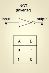 But how can a transistor be used as an INVERTER ?
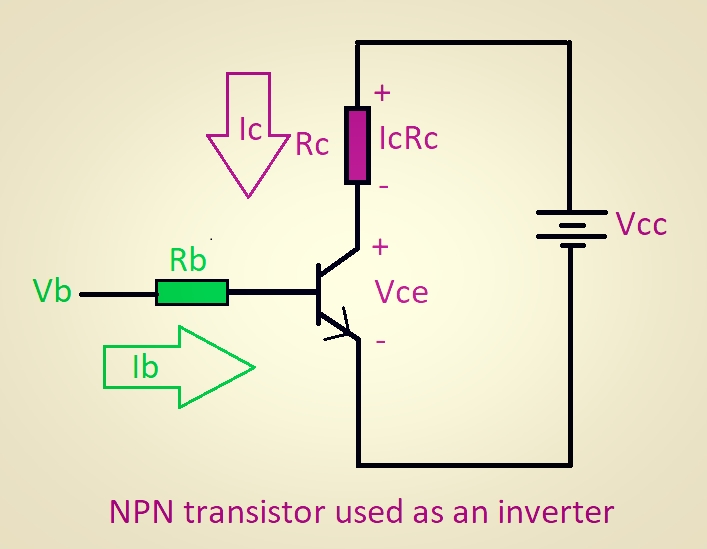 Consider an NPN transistor connected as shown in the above figure. There can be two cases when transistor is used as a switch.
Case 1 : Transistor is in cut off region
Consider an NPN transistor connected as shown in the above figure. There can be two cases when transistor is used as a switch.
Case 1 : Transistor is in cut off region
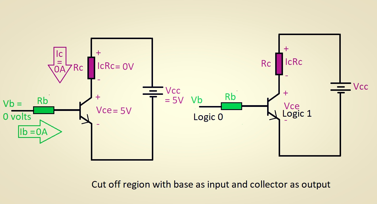
- When Vb (base voltage) is very low, the base current (Ib) will be negligible.
- Due to this, the collector current (Ic) will also be minimum and transistor will be in cut off region.
- As the collector current (Ic) is very low, there will be almost no voltage drop across resistance (Rc) thus IcRc = 0 volts
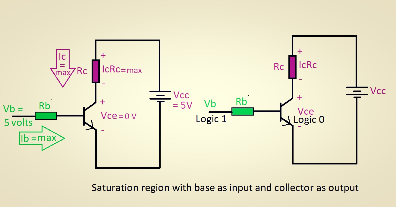
- When Vb (base voltage) is very high, the base current (Ib) will be maximum.
- Due to this, the collector current (Ic) will also be maximum and transistor will be in saturation region.
- That is, if we increase Ib, then Ic will also increase but, beyond a certain point Ic cannot increase and it will attain a maximum value.
- As the collector current (Ic) is very high, The voltage drop across Rc which is IcRc = very high
Thus if we summarize the following data we can infer that,
- When Vb = 0 volts (logic 0) , Transistor will be in cut off region. Vce = 5 volts (logic 1) . Transistor will act as an open switch.
- When Vb = 5 volts (logic 1) , Transistor will be in cut off region. Vce = 0 volts (logic 0) . Transistor will act as a closed switch.
Thanks for Reading guys 🙂 Recently my blog has reached 14,000 hits. This was possible only because of readers like you, who understand the hardships required to write science articles, As it requires a lot of research and plenty amount of time is invested. Writing this page and making pictorial explanations takes a lot of time and effort. If you like reading this blog, I would request you to follow my blog. Also visit my facebook page where I post some stuff related to electronics. Appreciate the support. 🙂 Link : https://www.facebook.com/Electroconcepts357/ You can also contact me on Quora where I have answered numerous questions and also have nearly 1.5 lakh answer views : https://www.quora.com/profile/Shashank-Shanbhag-5 Appreciate your support 🙂 -Shashank Shanbhag (Electronics engineer)

Could you please answer my other question
Output impedance is calculated by Vo/Io keeping Vin=0
But why input impedance is not calculated by keeping Vo=0
And how this method comes
LikeLike
Could you give me the whole context. As far as I know input impedance is calculated by keeping output voltage as zero. otherwise you cannot find input impedance. the output has to be shorted.
LikeLike
Nice blog!
Can you explain me that how the transistor is getting biased properly when Vce=0 volts?
LikeLike
Thanks for sharing such a beautiful article. It’s very helpful to me. Please keep more sharing about TRANSISTOR AS A SWITCH
LikeLiked by 1 person
Nicely explained
LikeLike